And still some resistance short on input. Ok, maybe the IRF
If with resistance short don't start even with low voltage. Find the shorted part/path first.
Ok. I load them with usual dummies and put 20 V on input and measure ovet TP?
Dude my LCR tells me I have 1000 uF over the 0,33 cap
On the the other board it says 0,42.
There is no need for dummies for CCS only test in low voltage. The shunt part won't get enough to reference up. Just return a crock cable to the voltage source from where the CCS tail ends and be sure you measure no resistance shorts. That one checking virtual capacitance I have no guide for.
Replacement of IRF840 didnt help, I got like 5 V out of it so I replaced the SK117, took some 430 ish value, and both KSA. Now the diode lits up nicely and it flows about the same voltage out as what I load it with, 315 V. Turning the VR doesnt seem to affect anything. Ideas?
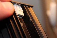
That is why proper CAT IV probes are either shrouded near to tip or twist isolating from CAT III to IV. So you can't arc with near items when probing HV.Here the lightning struck
Attachments

Replacement of IRF840 didnt help, I got like 5 V out of it so I replaced the SK117, took some 430 ish value, and both KSA. Now the diode lits up nicely and it flows about the same voltage out as what I load it with, 315 V. Turning the VR doesnt seem to affect anything. Ideas?
You mean the voltage trimmer? It can be easily dead too. There is not much contact material in there to sustain lightning or over-current.
Since you got one working unit start by measuring the static values that will give you a hint.
If you run out of parts i have several sets of sand and resistors for it but you´ll have make a trip out in the bush then
I measured different values both over trimmer and the KSA next to it. And I have lots of sand but a trip to the bush is always nice. I love that area and I would love to come over and bench some stuff or so when I have the opportunity.
Kokoretsi!
They didnt have, so that will have to be next time in Athens. Paidaka it was
I measured different values both over trimmer and the KSA next to it. And I have lots of sand but a trip to the bush is always nice. I love that area and I would love to come over and bench some stuff or so when I have the opportunity.
You´re very welcome just let me know a bit in advance so i can clean a path into the workroom
.Metaxa
Metaxa and HV don't blend well. Allow many hours after a few shots, else you will probe to Zeus caliber arcing.
- Home
- Amplifiers
- Tubes / Valves
- 6V6 line preamp