

you can blame only your self for that ........ matter of physical layout ;
if you proceed in that direction , you must place some local decoupling near tubes ; say that anything more than 10cm of wires between shunt reg and tubes is critical , in my book ;
how you'll do with high S toob ? you would have fireworks

My first thought was to use an umbilical from SSHVs to tubes as I have seen many people do here on 26 amps for example but I changed that idea in the middle of my test build when I saw Andrew T post something about that. So I putted the SSHVs just under the toobz instead. Those connects with 11-12 cm ethernet twisted pairs now.
All this info needs a burger to melt together with. Hotdogstand, here I come.
Last edited:
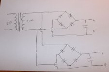
dunno for SSHV ground in/out topology ( Salas is da man for that ) but it seems to me that you must have separate diode blocks to chassis on both GND points on right side , deleting that existing one
you can't make half dual mono gadget , then make gnd loop with (usually) source having same gnd on both outputs ; that's same as little pregnant
if SSHV is having GND traces organization in perfect way , you are not having difference in potential between in and out GND and you can make it as shown
if case is different , each SSHV must have separate rectifier and filter
As far as I understand the SSHVs are just passing the ground thru, thats why I made it like this. Theres one PSU and two SSHVs with separately connecting audio grounds
Salas will know what to answer , even if I'm not doubting his layout
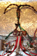
thought - more pics of your harness will not harm
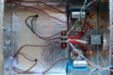
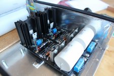
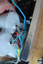
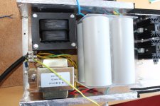
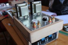
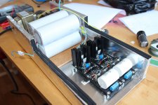
Heres some. Beware its a dummydoll, no comments of that please

First is PSU doll, second shows how I place the audio circuit on that, third trafo/filter side, 4th PSU star ground, 5th SSHVs, and 6th the audio circuit again.
I will do things in steps, starting I think with filament css to audio gnd point. Tho I know now that I made a mistake on that. Two LM317 is sharing same PSU. That means there could be the loop.
Attachments
My first thought was to use an umbilical from SSHVs to tubes as I have seen many people do here on 26 amps for example
Nobody does that. The regulator is placed as close as possible to the load. The umbilical cable is to bring power to the regulator.
Loud hum must be a ground loop.
I don't see the cathode chokes in the last picture. Those chokes if they're anywhere near the psu they'll pick a ton of 50Hz hum.
Second pic is the cathode chokes
what ground separation ?
there is no gnd separation needed for heating indirected heated toobz
If I am to try and connect the filament ground reference to the 2 audio ground stars instead of the single PSU ground star I need 2 separate grounds. Last time I connected the filament-CSS it had one common ground that was connected to single PSU ground. The dual LM317 had one common PSU/ground.
Or maybe I could just connect CSS PSU ground to big PSU ground and connect filament zero to each audio ground
Last edited:
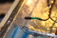
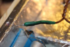
Ok. Im on chokes now. Didnt find any suitable shilding so im trying with twisting kathodechoke wires instead.
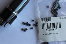
I've never messed with ferrite beads. I guess there must be isolation between them and the wire?
I had B+ voltage divider when I tried ac to filaments, even an adjustable one between 5-95 volts over gnd. Didnt make much of a difference, but it might do to css fed dc.
I've never messed with ferrite beads. I guess there must be isolation between them and the wire?
I had B+ voltage divider when I tried ac to filaments, even an adjustable one between 5-95 volts over gnd. Didnt make much of a difference, but it might do to css fed dc.
Last edited:
Cathodestoppers on chokewires in the form of dual ferrite beads mounted on both channels. Now to some professor balthasar walking around thinking of CSS circuit and potential divider.
Attachments
Last edited:
As far as I understand the SSHVs are just passing the ground thru
Correct. They just pass the ground doing no further tricks. You can even star ground them. When picturing them in a system think of the force 0 line carrying the PSU ground path to the load. Don't loop that twice at the load.
- Home
- Amplifiers
- Tubes / Valves
- 6V6 line preamp