Hello,
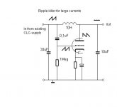
In a tubed SE-power amplifier I would like to use only non-polarised capacitors. I practiced already with Duncan designer to see what is the minimum I can get away with. As these caps are larger in volume compared to polarised electrolitics I would like to have them assisted somehow. On the site of Triode Dick I have found the so called ripple killer. This is a way to remove the ripple from the supply voltage. The enclosed schematics shows how this is achieved. The capacitor C4 of 100 nF allows high frequencies to pass to the grid of the ECC81. By adjusting potmeter P1 the ripple at the output can be minimised.
The original design of the ripple killer is made for application in a preamp. However, in my case I want to use this trick at a B+ of 450V. So the ECC81 should be replaced by some tube that can handle the voltage. I am thinking of an EL34 or the like. The EL34 can handle quite a lot of current. I do not want to regulate the voltage, on a relative or an absolute level.
Concrete the sequence of my power supply is: tubed bridge; secundairy 420V/200mA;
C = 2 uF, L1 = 8,5H/240 ohm and C = 20 uF; L2 = 6H/60ohm and 116 uF. With this mostly choke-input mode the output voltage is about 440V.
Also the current is much higher in a power amplifier. In my case this is about 100 - 150 mA.
The potmeter P1 of the ripple killer schematic would have to be of a high wattage type in my case. So again voluminous. And a large resistance in the B+ of an output tube is not desirable. The value of the resistance could be set lower, with the effect that less ripple can be killed. Another option is to use a choke instead of the potmeter: ‘a choked ripple killer’. In a way this reminds me of the so called tuned choke, but that tuning was done by a capacitor to optimise effectiveness of the choke.
Questions:
- Can you confirm that the ripple killer can also be used at a high voltage with a tube like the EL34? Does it require other wiring (I suppose the screen of this pentode should be connected to B+ )
- Can you comment on the most effective way to send as much ripple through the capacitor to the grid of the EL34 to kill as much ripple as possible? Will it have to be be a resistor, or is a ‘choked ripple killer’ an alternative? If so, how do I determine the optimal value of the choke.
Best, Arjen.
Attachments
This circuit isn't really suitable for scaling up for power amplifier use. By the time you have beefed up the power supply to take account of the amount of power necessarily consumed by the ripple-killer, you might as well have simply added another stage of LC smoothing to your existing supply. Also, it has significant output resistance - fine in a pre-amplifier but not good for a power amplifier.
Hello EC8010, others,
Thanks for the reply. I have now added a simple variant of the schematic in post 1. May be this one would be more suitable to cope with larger currents of say between 50 – 100 mA at 420 V in a tubed power amplifier? The idea behind it is that when you use a choke, why not get more out of it with some active device. The aim is to diminish the need for electrolitic capacitors and only use non-polarised ones. In comparison to the original ripple killer the potmeter is now exchanged for a choke. The ripple now can only be influenced some by changing the value of the choke.
The tube would have to be one that can absorbe the ripple. This will probably have to be an EL34 or the like.
Some questions:
- would this idea be interesting enough to experiment with?
- how to determine the power to be consumed by the tube?
- how to calculate the cathode resistor and bypass capacitor?
Can you comment please?
Best, Arjen.
Attachments
You'd have to try it to be certain, but I suspect that latest circuit will oscillate violently. The valve will see the choke as a high impedance anode load, and when there's 180 phase shift contributed by the choke and the grid's RC network, it will oscillate. This might be a genuinely useful application for SPICE...
rdf said:Shouldn't the grid be on the output side?
Crikey! I think you may have hit the nail on the head.
By the way, what is the source of your splendid avatar?
Hello EC8010, RDF, Others,
Thank you for your comments.
This last schematic was not from the Hindu-world and my background in EE is too little yet to design myself. I thought it was quite common and proven knowledge, as it can be found in several places. This schematic was from the site of Triode Dick: http://www.triodedick.com/ Look under projects, then 7th from below.
My quest through the internet had, and has, as a goal to rearrange the usual power supply schematic in order to use as little bipolar capacitance as usual, with the help of some active device. As the choke is there anyway, why not do something with it? The logic of a fool or not, new insights start with questions.
Hmm, but an oscillating device with the wrong connection would lead to nowhere.
Now I better reformulate my question: do you have a suggestion for an approach that would promise more succes? From there on it might develop to a schematic that is worth experimenting, in practice or in spice..
Best, Arjen.
I think you would probably do better using a tried and tested three-device regulator. I'm afraid I can't post a diagram at the moment, but you'll find the circuit everywhere. There is one device as the series pass element, another as the error amplifier, and another as the voltage reference. You can use a high voltage FET or a triode (1/2 6080) as your series pass element, and a pentode or high voltage transistor as your error amplifier. The reference could be an 85V Zener or an 85V neon reference (85A2). This will work.
EC8010 said:Crikey! I think you may have hit the nail on the head.
The files appear to be lost now but I Spiced quite a few variations on that theme, the best results I recall were from an EL34 with the screen driven from the 'input' side for a little positive-feedback ripple reduction. I'll eventually get around to trying this in the real world with a beam triode, probably driving the grid with a low level step-up transformer in paraphase.

By the way, what is the source of your splendid avatar?
A random Google search combined with a little post-editing. I think it was here: http://www.nndb.com/people/804/000092528/ . Would love to find the original.
EC8010 said:Thanks rdf. We don't have the "Three Stooges" here, but SY has told me about them.
In case you have your sound card working:
http://www.youtube.com/watch?v=YwP685FYnbI
http://www.youtube.com/watch?v=m46Vf_XMNNs
SY said:In case you have your sound card working:
I have a history of using a computer with a fancy sound card but no loudspeakers. The only way in which this has changed is that I now have two computers with fancy sound cards, but still no loudspeakers.
- Status
- This old topic is closed. If you want to reopen this topic, contact a moderator using the "Report Post" button.
- Home
- Amplifiers
- Tubes / Valves
- Choked ripple killer for SE?