I read this tubecad article a few days ago:
http://www.tubecad.com/2006/10/blog0082.htm
It's about using a tube circuit to stabilise a dc-voltage with the help of a transformer. The basic schematics provided in the article has dc flowing trough the transformer, meaning that a large airgapped transformer will be needed.
For a double sided supply my idea would be to even out the dc-currencies on both primary and secondary in the following way:
A good thing about using a push-pull arrangement is that the high-voltage supply's ripple will also cancel out. To ensure symmmetry the RC on the cathodes could be replaced with LM317 current taps.
When I first thought about how this would work I assumed that the ripple on + and - rails would have to be symmetrical and inverted in relation to eachother. This is usually the case after rectification.
Thinking further I realise that also a ripple on only one rail will be eliminated. If the circuit works as it's supposed to it will "copy" the ripple to the other side and cancel it out.
The case of symmetrical uninverted ripple will not be cancelled by the tube circuit but as the secondary currents flow trough the transformer in different directions it will to some extent cancel out in the transformer.
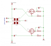
For this to work better a driver stage will probably be needed. But I have drawn a very simple schematic to illustrate how the circuit would work.
A small transformer and ECC82 tubes this could be used to regulate op-amp circuits. With more iron and real power tubes it could be used for power amplifiers.
Smart? It will not be cheap and it will not be efficient. And I'm not sure if it will hold any benefits compared to doing the same thing with solid state parts. And I'm not even sure if the circuit works. There can be holes in my logic. But I think it's a fun idea. It's allways nice when you can add tubes to a decice") .
.
http://www.tubecad.com/2006/10/blog0082.htm
It's about using a tube circuit to stabilise a dc-voltage with the help of a transformer. The basic schematics provided in the article has dc flowing trough the transformer, meaning that a large airgapped transformer will be needed.
For a double sided supply my idea would be to even out the dc-currencies on both primary and secondary in the following way:
- -On the secondary side, the voltages to be regulated are fed trough the windings with current flowing in opposite direction. As long as the current draw is symmetrical there will be no core saturation.
-On the primary side a push- pull arrangement is used instead of single-ended.
A good thing about using a push-pull arrangement is that the high-voltage supply's ripple will also cancel out. To ensure symmmetry the RC on the cathodes could be replaced with LM317 current taps.
When I first thought about how this would work I assumed that the ripple on + and - rails would have to be symmetrical and inverted in relation to eachother. This is usually the case after rectification.
Thinking further I realise that also a ripple on only one rail will be eliminated. If the circuit works as it's supposed to it will "copy" the ripple to the other side and cancel it out.
The case of symmetrical uninverted ripple will not be cancelled by the tube circuit but as the secondary currents flow trough the transformer in different directions it will to some extent cancel out in the transformer.
For this to work better a driver stage will probably be needed. But I have drawn a very simple schematic to illustrate how the circuit would work.
A small transformer and ECC82 tubes this could be used to regulate op-amp circuits. With more iron and real power tubes it could be used for power amplifiers.
Smart? It will not be cheap and it will not be efficient. And I'm not sure if it will hold any benefits compared to doing the same thing with solid state parts. And I'm not even sure if the circuit works. There can be holes in my logic. But I think it's a fun idea. It's allways nice when you can add tubes to a decice
.Attachments
Yes, the article I refer to also recommends a driver stage. Maybe an ECC83 driving an ECC82 or ECC88 based output stage.
In a way this is also a very stupid idea... why build a tube amplifier to regulate an SS-amp's psu? Why not get rid of the SS-stage and use the tube stage instead?
But all crazy ideas are not bad ideas....
In a way this is also a very stupid idea... why build a tube amplifier to regulate an SS-amp's psu? Why not get rid of the SS-stage and use the tube stage instead?
But all crazy ideas are not bad ideas....
thomsva said:Yes, the article I refer to also recommends a driver stage. Maybe an ECC83 driving an ECC82 or ECC88 based output stage.
In a way this is also a very stupid idea... why build a tube amplifier to regulate an SS-amp's psu? Why not get rid of the SS-stage and use the tube stage instead?
But all crazy ideas are not bad ideas....
I think John's point is to use an output transformer to regulate AC ripples. This may be a different (or better -- I have no idea) way to do voltage regulation. Normally, something like a Jung Super Reg will be used, with the pass element being a transistor.
Assuming that the basic circuit works there are still many open questions:
1. Optimal transformer windings ratio? John Broskie's article thinks mostly in the terms of maximum ripple voltage compared to maximum voltage swing of the tube. Is there more to it than that?
2. Should filter capacitors be placed before/after the regulator? How much capacitance?
3. Can the circuit become an oscillator if the bandwidth of the transformer is too limited (leading to phase shift)? Should HF be filtered away from the grids to avoid this?
4. Could the push-pull stage be biased to work in class AB or B without degraded quality or other major problems?
I have e-mailed my schematic to John Broskie, but he hasn't replied within a couple of days. It would be very nice to read more from him about the subject.
What is wrong with us Finnish?
You want to build SS amplifer with tube PSU and I want build tubeamplifier with switching mode PS.
But what is your goal? With tube you can get high voltage and with SS you can handle high currents. Do you want to get worst of both worlds?
Anyway that is very interesting idea and so grazy that might even work brilliantly.
- Status
- This old topic is closed. If you want to reopen this topic, contact a moderator using the "Report Post" button.
- Home
- Amplifiers
- Tubes / Valves
- Tube regulator for solidstate devices