Hi all,
Finally making a bit of progress on this P-P amp I seem to have been working on forever. (not helped by rather more travelling than can be good for you)
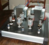
Just now I'm looking at the orientation of the "amp part" so I can get the metalwork done. The "power part" is separate. so no pesky power transformers to worry about.")
I have a couple of choices for OPT orientation, and I'm looking really for the minimum crosstalk here best is to orientate them with bells or laminations together?
so photo1: bells together
edit: re-wrote in English
Finally making a bit of progress on this P-P amp I seem to have been working on forever. (not helped by rather more travelling than can be good for you)
Just now I'm looking at the orientation of the "amp part" so I can get the metalwork done. The "power part" is separate. so no pesky power transformers to worry about.
I have a couple of choices for OPT orientation, and I'm looking really for the minimum crosstalk here best is to orientate them with bells or laminations together?
so photo1: bells together
edit: re-wrote in English
Attachments

SY - I guess that with the laminations facing each other the trafo's are 'marginally' closer together.. these are erm 'somewhat' over specced tho - I guess I'm just not going to worry about it...
Cool! no overiding objections to the layout generally preffered, how often does that happen!?
gold_xyz - schematics yeah, well, when I know you can bet you will... Its a fairly vague development process... I have key parameters set and so on but when I think I have something workable I'll embarass myself here and find out I don't... [seriously this is how it works!] Basically its a variation on the Williamson circuit, bit more direct coupled, LOT more semiconductors... still input, phase splitter, buffer, output.
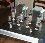
Waveborne - hottest tubes are not closer to edges because the edges are massive heatsinks for the ccs's etc - it was a trade off. My original thoughts paralleled your own (plus I thought it looked better that way) but it's just too darn handy to pop the sand on a heatsink. The output stage is "fixed" (servo so far) bias, needing to be able to cope with a variety of tubes and my goldfish like attention spa...
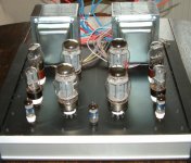
Speaking of heat dissipation though... an alternative arrangement attached here = how rigid do you think is the 4" ctrs for the kt88 are? I can manage 3.5" in this way. But according to the datasheet thats NBG... I know Ive seen "McIntosh" amps with waaay under that (they were in China hence the " ")
And yes I know starting with a chassis is not the best engineering way but I needed something "acceptable" so please dont beat me up too much for starting in reverse
Andy
Cool! no overiding objections to the layout generally preffered, how often does that happen!?
gold_xyz - schematics
yeah, well, when I know you can bet you will... Its a fairly vague development process... I have key parameters set and so on but when I think I have something workable I'll embarass myself here and find out I don't... [seriously this is how it works!] Basically its a variation on the Williamson circuit, bit more direct coupled, LOT more semiconductors... still input, phase splitter, buffer, output.Waveborne - hottest tubes are not closer to edges because the edges are massive heatsinks for the ccs's etc - it was a trade off. My original thoughts paralleled your own (plus I thought it looked better that way) but it's just too darn handy to pop the sand on a heatsink. The output stage is "fixed" (servo so far) bias, needing to be able to cope with a variety of tubes and my goldfish like attention spa...
Speaking of heat dissipation though...
an alternative arrangement attached here = how rigid do you think is the 4" ctrs for the kt88 are? I can manage 3.5" in this way. But according to the datasheet thats NBG... I know Ive seen "McIntosh" amps with waaay under that (they were in China hence the " ") And yes I know starting with a chassis is not the best engineering way but I needed something "acceptable" so please dont beat me up too much for starting in reverse
Andy
Attachments
- Status
- This old topic is closed. If you want to reopen this topic, contact a moderator using the "Report Post" button.