I have a MingDa MC-7R preamp that has a couple of issues
- too much gain
- a bit too much noise even a minimum volume.
I've swapped the preamp tubes (2* 12AX7) and output tubes (2* 12AU7) but it's had no improvement in noise.
Noise seems to have 2 components - (hissing that is volume level dependent; and buzz which is volume level independent).
I've also tried 5751 (mu=70) in place of the 12AX7 but the gain is still about the same.
The point to point wiring all looks good and should lend itself to easy mods.
I feel the noise and gain issues are related.
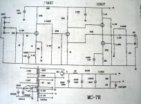
Please see the circuit diagram and suggest how I can reduce the gain/noise.
Many thanks.
- too much gain
- a bit too much noise even a minimum volume.
I've swapped the preamp tubes (2* 12AX7) and output tubes (2* 12AU7) but it's had no improvement in noise.
Noise seems to have 2 components - (hissing that is volume level dependent; and buzz which is volume level independent).
I've also tried 5751 (mu=70) in place of the 12AX7 but the gain is still about the same.
The point to point wiring all looks good and should lend itself to easy mods.
I feel the noise and gain issues are related.
Please see the circuit diagram and suggest how I can reduce the gain/noise.
Many thanks.
Attachments
Hi
I just cannot imagine what kind of person designs these circuits. So many stages? For what? If it was mine i'd preserve the PS and chasis and cut down to a single 12B4.... As this is probably not what you want let's see if it can be improved.
Swapping different tubes will have minimal effect on gain due to global NFB. It seems set to 23 at present, which for a line stage is absurdly high. By reducing the 22k resistor you can also reduce the gain but at usefully low values the circuit may oscillate, you just have to experiment but not into your power amp and speakers. I find that gain above 4 is unnecessary and only contributes to higher noise.
If your source has no dc you can also remove the input coupling cap.
I am anything but an amplifier expert, but what is the purpose of the 12AU7? It looks to me you could completely take it out, and it wouldn't affect the circuit in any way.
I see a high gain cathode biased triode, cap coupled to a cathode follower. From there, it feeds directly to the output. The 12AU7 isn't even in the circuit? Or does it connect up to the 330K output (difficult to see). Either way, it seems like you would be better off just pulling that tube and shorting out the 330K, maybe throwing in a 100 ohm instead.
I see a high gain cathode biased triode, cap coupled to a cathode follower. From there, it feeds directly to the output. The 12AU7 isn't even in the circuit? Or does it connect up to the 330K output (difficult to see). Either way, it seems like you would be better off just pulling that tube and shorting out the 330K, maybe throwing in a 100 ohm instead.
zigzagflux said:Either way, it seems like you would be better off just pulling that tube and shorting out the 330K, maybe throwing in a 100 ohm instead.
Hmm. No. The second 12AX7 is in common cathode as shown. The purpose of the 330k is most likely to help stabilise dc operating point.
A 12AX7 will make an extremely poor cathode follower. Not that it hasn't been done.
Removing that 1000uF cap in the first stage will both reduce local stage gain and the overall closed loop gain to about 6. Verify that it is stable under these conditions (with a scope) before connecting amplifier or speakers to it.
If you do this mod use a 5751, the lower mu should help with stability.
I just realized there is another sneaky thing you can do to reduce loop gain further without changing the quiescent operating point. Replace the 270K plate load resistor with 100K and the 100K dropping resistor with 270K.
If you do this mod use a 5751, the lower mu should help with stability.
I just realized there is another sneaky thing you can do to reduce loop gain further without changing the quiescent operating point. Replace the 270K plate load resistor with 100K and the 100K dropping resistor with 270K.
Thanks for the suggestions.
Agreed, the circuit seems overly complicated.
I'll try to reduce the 22k feedback resistor. At the moment I cannot even get past 9'oclock on the volume pot before it's way too loud!
However to be safe I prefer to leave the DC blocking cap in place.
Good point about the 12Au7's, I can't really see what their purpose is?
The 12AU7A is a white cathode follower and is the output section of your pre-amplifier and hence is necessary. The 330K resistor is providing some feedback probably to help keep the follower centered.
Not totally clear looking at the schematic.
You really don't want to decrease the value of that 22K feedback resistor very much as that increases the amount of current the output has to source and depending on the operating current in the output stage may result in poorer linearity.
The network to the second 12AX7A can be modified (2.2M, 270K and 1M) to reduce gain as well. Change that 1M resistor to say 270K for a further 6dB reduction in gain.
I'd remove the previously mentioned 330K resistor, its positive feedback, not negative. I suspect it may increase overall gain slightly in fact. I'd also ditch that 2.2M resistor right after the coupling cap from the first to second stage.
I'm very sorry but the supplied schematic does not correspond to the actual amp's circuit.
The 1K resistor out of the first 12AX7 is actually 2.2K.
And the 100uF cap in parallel with the 820ohm resistor on the 12AU7 is actually 22nF.
Now I' more concerned about the quality of this amp!
Anyway I made some changes.
I reduced this 1M resistor to 280K (by adding a 390K in parallel since it was in an awkward location to desolder). But it had no effect on the gain. I'm confused.
Leaving the previous mod in place, I have removed the 2.2M resistor. But this again did not have any effect! More confused.
BTW my method of testing could be suspect. I only made the above mods on the same single channel. Then I'm playing a constant 315hZ tone and measuring the preamp outputs. Both the modified and unmodified channels show the same output voltage to within 0.1%.
I'm hesistant to try the NF mods yet since I don't have a scope to check for oscillation.
Thanks again.
The 1K resistor out of the first 12AX7 is actually 2.2K.
And the 100uF cap in parallel with the 820ohm resistor on the 12AU7 is actually 22nF.
Now I' more concerned about the quality of this amp!
Anyway I made some changes.
kevinkr said:
The network to the second 12AX7A can be modified (2.2M, 270K and 1M) to reduce gain as well. Change that 1M resistor to say 270K for a further 6dB reduction in gain.
I reduced this 1M resistor to 280K (by adding a 390K in parallel since it was in an awkward location to desolder). But it had no effect on the gain. I'm confused.
kevinkr said:
I'd remove the previously mentioned 330K resistor, its positive feedback, not negative. I suspect it may increase overall gain slightly in fact. I'd also ditch that 2.2M resistor right after the coupling cap from the first to second stage.
Leaving the previous mod in place, I have removed the 2.2M resistor. But this again did not have any effect! More confused.
BTW my method of testing could be suspect. I only made the above mods on the same single channel. Then I'm playing a constant 315hZ tone and measuring the preamp outputs. Both the modified and unmodified channels show the same output voltage to within 0.1%.
I'm hesistant to try the NF mods yet since I don't have a scope to check for oscillation.
Thanks again.
They should show the same output level, all you have done is reduce the internal loop gain, the external feedback components still set the overall gain.
Try removing the cathode bypass cap (1000uF) on the first 12AX7A, this should reduce the gain to about 6.
Changes not reflected in a schematic are not uncommon, usually done to address some issue discovered after the initial design has been done and production started. Sometimes it takes a while for documentation to catch up. (And unfortunately sometimes that never happens.)
Thanks Kevin!
I've removed the 100uF bypass cap (not easy to read from the schematic!).
Now the channels are showing different output voltages.
The gain is indeed about 6.
This is a much more practical value in my setup.
Can I revert the internal loop gain mods and have just the removed bypass cap mod?
(Since I've only made these changes to one channel, it's easier for me leave the original parts alone)
I want to test this stability further before connecting to the main rig.
Is there other tests (albeit I'm only limited to a multimeter and a collection of test tones) that I can perform?
I very much appreciate your patience with this noobie!
Hi, you need to keep the internal loop mods along with the change reducing closed loop gain to 6. My intention was to assure stability at the lower closed loop gain by also reducing the open loop gain. I meant the changes to "play" together.
Some argue the benefits of large amounts of feedback in an amplifier circuit, here due to the relatively limited open loop bandwidth I prefer as little loop feedback as possible. In my experience (and opinion) this should result in a more open sound.. FWIW
Some argue the benefits of large amounts of feedback in an amplifier circuit, here due to the relatively limited open loop bandwidth I prefer as little loop feedback as possible. In my experience (and opinion) this should result in a more open sound.. FWIW
Spent a bit of time testing this setup for stability so had delayed connecting up the good speakers.
Result: thrilled!
The hiss is much reduced, only by really ear to tweeter at high volumes am I hearing anything. The buzzing is also lower than before.
With music there is certainly more sense of air and palpability to the performance. Wonderful!
Thank you so much Kevin!
Result: thrilled!
The hiss is much reduced, only by really ear to tweeter at high volumes am I hearing anything. The buzzing is also lower than before.
With music there is certainly more sense of air and palpability to the performance. Wonderful!
Thank you so much Kevin!
Hi Hirafu,
You're very welcome. I'm glad I was able to help. I used to do a lot of mods on badly designed commercial hifi - it was the life blood of my business in the early days. The schematic you furnished was very helpful. Some of my early designs were a little similar. I've moved on, these days I work for a large ATE firm, and do a little audio design/consulting on the side.
Kevin
Hi Hirafu_boarder.
I also own a Ming da MC-7R and have the same problems as you did. I'll hopefully be implementing Kevinkr's set of mods next week, but there's a few little things I'm not sure about.
I was wondering if you'd be willing to post any pictures of your mods?
Many thanks.
- JohnM
I also own a Ming da MC-7R and have the same problems as you did. I'll hopefully be implementing Kevinkr's set of mods next week, but there's a few little things I'm not sure about.
I was wondering if you'd be willing to post any pictures of your mods?
Many thanks.
- JohnM
Hi John,
I've been vacationing in Cambodia the past week or so, hence the lack of response.
Anyway the Meixing is on loan to a friend at the moment, so I cannot provide photos.
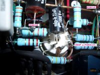
I do have a photo before I did the mods and it captures most of the images needed.
However the mods suggested by Kevin are pretty straightforward to carryout.
Removing the 2.2M resistor is easiest.
Kevin suggested reducing the 1M resistor to 270K, but I had some 390K resistors, so I parallel them with the 1M left in place (this should be equiv to 280K).
The 100uF electrolytic cap was in a difficult place to remove, so you'll need to temporarily move the overhead cap if want to remove the electrocap by desoldering (or you could just snip it out).
Cheers.
I've been vacationing in Cambodia the past week or so, hence the lack of response.
Anyway the Meixing is on loan to a friend at the moment, so I cannot provide photos.
I do have a photo before I did the mods and it captures most of the images needed.
However the mods suggested by Kevin are pretty straightforward to carryout.
Removing the 2.2M resistor is easiest.
Kevin suggested reducing the 1M resistor to 270K, but I had some 390K resistors, so I parallel them with the 1M left in place (this should be equiv to 280K).
The 100uF electrolytic cap was in a difficult place to remove, so you'll need to temporarily move the overhead cap if want to remove the electrocap by desoldering (or you could just snip it out).
Cheers.
Attachments
- Home
- Amplifiers
- Tubes / Valves
- MingDa MC-7R noise and gain