I would like to build my first pp; a 6as7 circuit to suit the tubes and opts I already have
You might like to check out http://www.wimdehaan.nl/tubeamps/6as7g/index.html for a PP design using the 6AS7G yielding 10W at 0.26% distortion with only 8dB feedback. Design uses a common 3K4 output transformer.
Wim
wimdehaan said:
You might like to check out http://www.wimdehaan.nl/tubeamps/6as7g/index.html for a PP design using the 6AS7G yielding 10W at 0.26% distortion with only 8dB feedback. Design uses a common 3K4 output transformer.
Wim
How is the bass with only 100uF caps in the cathode bypass on the 6as7?
to wimdehaan
6as7 are known to have mismatched triodes.
is there a way to matched them in the circuit?
some designs I've seen (e.g. andrea ciuffuli's pse EL34) uses separate bias for each of the triode.
also since there is no power supply schematic provided, can you tell me what did you use?
thank you.
6as7 are known to have mismatched triodes.
is there a way to matched them in the circuit?
some designs I've seen (e.g. andrea ciuffuli's pse EL34) uses separate bias for each of the triode.
also since there is no power supply schematic provided, can you tell me what did you use?
thank you.
wimdehaan said:
You might like to check out http://www.wimdehaan.nl/tubeamps/6as7g/index.html for a PP design using the 6AS7G yielding 10W at 0.26% distortion with only 8dB feedback. Design uses a common 3K4 output transformer.
Wim
Hi wim.
some questions in regards to your design.
1. 6as7 are known to have mismatched triodes. is there a way to matched them in the circuit? some designs I've seen (e.g. andrea ciuffuli's pse EL34) uses separate bias for each of the triode.
2. Also since there is no power supply schematic provided, can you tell me what did you use?
3. If I decided to double the number of output triodes, what changes are involved?
4. Where is the +LS and -LS connected? are they connected to the speakers? Is the +LS that is connected to the white lead the 8hm output? if I connect it to the other output lead, how do I calculate R28?
5. is there any advantage to using lower voltage on V1 to V4 so I do not have to use high value resistance to drop the voltage to required levels? I know that the drawback is the possible requirement of another secondary to provide the lower voltage.
6. since you are using a negative supply for the CCS, did you connect the ground of the -12 supply to the B+ ground?
thank you.
thank you the help
")
Originally posted by jarthel
Hi wim. some questions in regards to your 6AS7G design.
Answer 1: yes, many 6AS7 are really mismatched, even RCA types. Using P3 you can adjust the balance. I am using a small 100uA-0-100uA meter (needle in the middle) for optical adjust for balance, this works good. BTW on Ebay there is a german perosn who sells russian 6AS7 as matched pairs for not too much. I have a few, but never tried them. I have some RCA's doing the job.
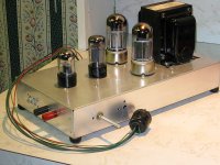
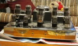
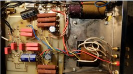
Answer 2: I did update the website, the PSU is now available as PDF file. I am using a straightforward design using 2 chokes as can been seen in the photos. Important thing to know is that the cathode of the E88CC is not related to ground but to +190V, so this heater has to be floating from ground, I am using a 1uF film cap to ground the heater.
Answer 3: the primary impedance of the output transformer, for 4 tubes in PP 1,9K would be an option. Mine is using 2 in PP, and it is loud enough. I would not recommend 4 tubes.
Answer 4: LS is loudspeaker. This transformer has 4, 8 and 16 ohm out (and 2 ohm I believe), I am using the 4 ohm output. R28 is a divider with R5 (approx. Uo/Ui= R5/ R+R9). 8 dB feedback I found is a good compromise in with and without feedback. I prefer without, but the 6AS7 needs some to make it measure okay. For R9 I use in the test setup an adjustable resistor and using a AC meter it is easily set for 8 or 10 or 12 dB FB.
Answer 5: V1 to V4 are very critical. The 6AS7G needs an enormous voltage to drive them. I believe it was 80 or 90V AC RMS (neg. bias voltage is -134V). Will check if you want to know for sure. It is a very insufficient tube and difficult to handle, in some design on some website they gave up because of no good overall results in distortion. I tried many driver tubes and the E88CC shows best overall result, according to many DIY people this tube doesn’t ‘sound’, I feel the same, but many people listened to this amp (of course including me) and they (and me) can’t ‘hear’ the E88CC. I am using the new made JJ Electronics.
Answer 6: Yes the ground of the CCS is connected to B+ ground, in this design I strictly use star-ground, so many ground wires in this amp.
BTW the CCS for the E88CC is essential without (so using a common resistor) specs are going badly the wrong way. Other clue, is the 150 ohm resistor in the output stage, if you have a distortion analyser you might like to check the behaviour of the 15 cents component ;-)
Wim
The Russian 6H13C are softer and less detailed sounding than the RCA's. If feedback is employed I would quess there wouldn't be much in it. The 6H13C's look nicer though.
My 6080 amp got a good reception at a local meet at the weekend. The 6080's are not disappointing.
Shoog
My 6080 amp got a good reception at a local meet at the weekend. The 6080's are not disappointing.
Shoog
wimdehaan said:
Answer 1: yes, many 6AS7 are really mismatched, even RCA types. Using P3 you can adjust the balance. I am using a small 100uA-0-100uA meter (needle in the middle) for optical adjust for balance, this works good. BTW on Ebay there is a german perosn who sells russian 6AS7 as matched pairs for not too much. I have a few, but never tried them. I have some RCA's doing the job.
so with the amp meter, how do you adjust it so they match? to make it balanced, does the needle have to be in the middle?
wimdehaan said:
Answer 3: the primary impedance of the output transformer, for 4 tubes in PP 1,9K would be an option. Mine is using 2 in PP, and it is loud enough. I would not recommend 4 tubes.
is the impedance the only changes? How do I connect the extra tubes to the circuit? any chance of a new schematic/drawing?
wimdehaan said:
Answer 5: V1 to V4 are very critical. The 6AS7G needs an enormous voltage to drive them. I believe it was 80 or 90V AC RMS (neg. bias voltage is -134V). Will check if you want to know for sure. It is a very insufficient tube and difficult to handle, in some design on some website they gave up because of no good overall results in distortion. I tried many driver tubes and the E88CC shows best overall result, according to many DIY people this tube doesn’t ‘sound’, I feel the same, but many people listened to this amp (of course including me) and they (and me) can’t ‘hear’ the E88CC. I am using the new made JJ Electronics.
I may have been unclear with my question.
Is there any advantage to having a separate B+ for the V1 to V4. So I have say a 195V supply and another 383V supply.
wimdehaan said:
Answer 6: Yes the ground of the CCS is connected to B+ ground, in this design I strictly use star-ground, so many ground wires in this amp.
how about the negative supply? where is it ground connected? did you leave it "hanging"?
new question: what transistors did you use to make up the CCS?
thank you for the help
Originally posted by Jarthel
Answer 1: yes, many 6AS7 are really mismatched, even RCA types. Using P3 you can adjust the balance. I am using a small 100uA-0-100uA meter (needle in the middle) for optical adjust for balance, this works good. BTW on Ebay there is a german perosn who sells russian 6AS7 as matched pairs for not too much. I have a few, but never tried them. I have some RCA's doing the job.
so with the amp meter, how do you adjust it so they match? to make it balanced, does the needle have to be in the middle?
Yes, when the meter is in the middle both sections conduct the same current.
Originally posted by Jarthel
Answer 3: the primary impedance of the output transformer, for 4 tubes in PP 1,9K would be an option. Mine is using 2 in PP, and it is loud enough. I would not recommend 4 tubes.
is the impedance the only changes? How do I connect the extra tubes to the circuit? any chance of a new schematic/drawing?
I would not do so, driver stage will be stressed. In my home the 2 tubes makes a lot of 'noise', it's loud enough.
Originally posted by Jarthel
Answer 5: V1 to V4 are very critical. The 6AS7G needs an enormous voltage to drive them. I believe it was 80 or 90V AC RMS (neg. bias voltage is -134V). Will check if you want to know for sure. It is a very insufficient tube and difficult to handle, in some design on some website they gave up because of no good overall results in distortion. I tried many driver tubes and the E88CC shows best overall result, according to many DIY people this tube doesn’t ‘sound’, I feel the same, but many people listened to this amp (of course including me) and they (and me) can’t ‘hear’ the E88CC. I am using the new made JJ Electronics.
I may have been unclear with my question.
Is there any advantage to having a separate B+ for the V1 to V4. So I have say a 195V supply and another 383V supply.
In a way not. If you look at the PSU you will see, that the driver stage has it's own RC network.
Originally posted by Jarthel
Answer 6: Yes the ground of the CCS is connected to B+ ground, in this design I strictly use star-ground, so many ground wires in this amp.
how about the negative supply? where is it ground connected? did you leave it "hanging"?
To the central earth.
Originally posted by Jarthel
new question: what transistors did you use to make up the CCS?
thank you for the help
I am using the BC550B.
Wim
Hi All,
I'm quite interested about this project too. Also I found an unusual schematic http://www.dhtrob.com/schemas/afbeeldingen/6as7pp.gif which the plates of the driver stage are inverted connected to the UL-taps of the OPT's. Is there any advantage or disadvantage? What would be the output wattage? Thanks.
mus
Bonjour,You might like to check out 404 Not Found for a PP design using the 6AS7G yielding 10W at 0.26% distortion with only 8dB feedback. Design uses a common 3K4 output transformer.
Wim
The link to the schematic has disapared.
Has someone keeped the schematic,please ?
I got a 3,5k pp opt and 6n5s tubes...
Last edited:
Try this web archive link:
https://web.archive.org/web/20090219083510/http://wimdehaan.nl/downloads/6as7gppcircuit.pdf
https://web.archive.org/web/20090219083510/http://wimdehaan.nl/downloads/6as7gppcircuit.pdf
Try this web archive link:
https://web.archive.org/web/20090219083510/http://wimdehaan.nl/downloads/6as7gppcircuit.pdf
Thanks a lot!
I understand the phase spliter and drivers stages.
But the power stage astonished me:
Should i understand that 6AS7g are realy feeded with 250v?
Driving the 6080/6AS7 Made Easy
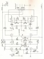
Trying bootstrapping with both 20% & 43% UL OPT's, indicated low mu tubes could be easily driven. I tried the cct with a single 6080 on the bench. The trial looked promising. The final amp using two 6080's is in the attached. It was a proof of concept experiment. I did not complete an entire amp.
As is on a 400V supply two 6080's manage an easy 25W. The OPT is a Hammond 1650N, wound for one half the regular OPT, so 2150 Ohms. Part number is H300429. The DF without NFB measured 3. With 13 db NFB the DF was 15.
An article covering this amp was published in Glass Audio, Volume 11, Number 2, May 1999.
Hi mus,
This is a kind of bootstrap who was suggested long time ago by John Stewart (another canadian guy IIRW).
The effect is to artifically increase the plate supply of the driver tube excatly like in McIntosh.
Yves.
Trying bootstrapping with both 20% & 43% UL OPT's, indicated low mu tubes could be easily driven. I tried the cct with a single 6080 on the bench. The trial looked promising. The final amp using two 6080's is in the attached. It was a proof of concept experiment. I did not complete an entire amp.
As is on a 400V supply two 6080's manage an easy 25W. The OPT is a Hammond 1650N, wound for one half the regular OPT, so 2150 Ohms. Part number is H300429. The DF without NFB measured 3. With 13 db NFB the DF was 15.
An article covering this amp was published in Glass Audio, Volume 11, Number 2, May 1999.
Attachments
Boot Strapping Without the UL OPT
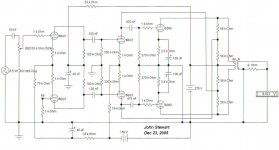
While working on the bootstrapped drive for the 6080 I realized it was possible without the UL taps. Here it is using an ordinary OPT. This was bench tested & simulated with good results. The bootstrap is 1/2 the 6080 plate signal, the 6SN7 load looks like 28K, bootstrapped.
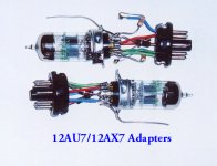
In other trials I'd found the 6BQ7 delivered results near as good as the very expensive 6SL7s & 6SN7s. I had built adapters for the trials. And made the wiring changes to try the 6BQ7s.
While working on the bootstrapped drive for the 6080 I realized it was possible without the UL taps. Here it is using an ordinary OPT. This was bench tested & simulated with good results. The bootstrap is 1/2 the 6080 plate signal, the 6SN7 load looks like 28K, bootstrapped.
In other trials I'd found the 6BQ7 delivered results near as good as the very expensive 6SL7s & 6SN7s. I had built adapters for the trials. And made the wiring changes to try the 6BQ7s.
Attachments
Hi All,
I'm quite interested about this project too. Also I found an unusual schematic http://www.dhtrob.com/schemas/afbeeldingen/6as7pp.gif which the plates of the driver stage are inverted connected to the UL-taps of the OPT's. Is there any advantage or disadvantage? What would be the output wattage? Thanks.
mus
Another look at this thread today I see reference to the circuit I proposed in 1999. But the schematic actually has the gain control hooked up backwards. And as always, no mention of the origin of the bootstrapping.
A few years ago I was contacted by someone who bought an amp based on the bootstrapped idea. The amp had failed, the builder went cheap on the 6AS7 cathode resisters. The amp smoked a bit & almost caught fire. Built in Bankok.
The idea has now been in circulation for more than 20 years, one would think more amateurs would have used it. But people still persist in building complicated brute force drivers in spite of the far better boot strapping system. Some refer to it as positive FB, a circuit they want to avoid. But their reasons are not well documented. I'll add something to this later.
Attachments
- Status
- This old topic is closed. If you want to reopen this topic, contact a moderator using the "Report Post" button.
- Home
- Amplifiers
- Tubes / Valves
- Please help amend 6AS7PP circuit