I've been buiding amps for each of the nieces. 3 down, 2 to go.
Niece #3 - Jessica's Amp - using irfanview to get file size right - hope it readable.
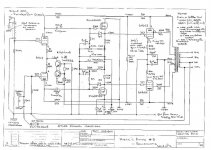
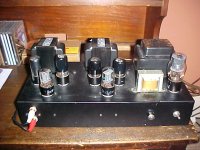
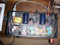
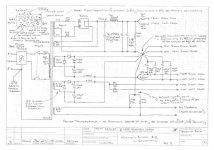
Similar to "Kates Amp" in the "Baby Huey" thread but this time went for tube rectifier and a choke in the HV supply. Those big blue bombs in the underside pic below are 60uF/900V polypropylene final HV caps.
The "trick" to getting this one to sound great was to balance local and global feedback. Local is about 6dB and global is about 4dB.
Cheers,
Ian
Niece #3 - Jessica's Amp - using irfanview to get file size right - hope it readable.
Similar to "Kates Amp" in the "Baby Huey" thread but this time went for tube rectifier and a choke in the HV supply. Those big blue bombs in the underside pic below are 60uF/900V polypropylene final HV caps.
The "trick" to getting this one to sound great was to balance local and global feedback. Local is about 6dB and global is about 4dB.
Cheers,
Ian
Attachments
")
Ray,
the ZVN0545A is a 450V 90mA continuous 0.6 Watt rated E-Line device with:
Ciss (Input Capacitance) 70pF
Coss (Output caapcitance) 10pF
Crss(Reverse Transfer Capacitance) 4 pF
The IRF820 is 500V 2.5A continuous device with:
Ciss (Input Capacitance) 360pF
Coss (Output caapcitance) 61pF
Crss(Reverse Transfer Capacitance) 6 pF
It is a really good "Rule of Thumb" when considering device capacitance in a design to never use a larger device than what is required.
This is where I got a bit of cross over from the day job. I used ZVN0545A to switch 300V gating pulses into a photomultiplier tube for a Laser Receiver.
You could argue that the Ciss is not a problem for a Source Follower and that arguement is correct as far as it goes, however the modulation of Ciss with changing Vds maybe, also modulation of Crss, so start with a lower capacitance device and allow enough voltage on the Drain such that VDS is kept to a minimum of say 25V on positive going signal peaks. I did'nt manage to do that because of limitations in the windings available on the power tranny BUT the choice of the low capacitance MOSFET will have minimised these effects.
On the local feedback level - Its not as big as you might expect from that 30K cross coupling resistor. Thats because the feedback voltage developed across that resistor is divided by the rp of the 6SL7 which is not really high enough. I did have more local feedback than shown with no global feedback but the amp sounded like a good Solid State Amp and we can't have that. So I backed it off which opened up the sound and made it more dynamic and then compensated for increased Zout by applying a very small amount of global feedback.
Cheers,
Ian
Gigertube, I love your Baby Huey. I'm on my third version now -- fixed bias, Edcor output transformers, eBay toroidal power transformer. I've tried a number of things in the last year; but other than the fixed bias, I've come back to your original design everytime.
How do you compare this design to your Baby Huey?
How do you compare this design to your Baby Huey?
ctaudio and others,
For simplicity the ECC803S diffamp and the Ultralinear EL84 outputs remains the definitive circuit and is a better performer than the "Jessica" Amp presented here.
Having said that, they sound quite different and this amp has a gloriousness all of its own - its a great Rock and Blues Amp whereas the original EL84 version is better overall across all music selections.
I think the power supply choke and polyproylene HV caps are a plus for this amp which could be applied to the EL84 Amp.
Reasons why the original EL84 amp is "better":
The "Baby Huey" Shunt feedback scheme relies on trading off output tube gm for reduced rp and so will always work best with higher gm output tubes such as the EL34, EL84, KT77, KT88 rather than tubes like 6V6, 5881,6L6.
Aside: I had new JJ 6V6s in this amp but couldn't get it to sound the way I wanted it. The Taylor 45D tube tester showed why - the new JJ 6V6s test at gm between 2.0 and 2.5 mA/V (Tube Manuals say new spec for 6V6 is 4.1mA/V). I then pulled out my stash of about 30 old 6V6GT (Used and NOS) and selected 4 with identical gm of 3.9 mA/V. I had hoped to use 6V6G (the Coke Bottle Shaped jobs) but only had 7 and could'nt get 2 good matched pairs from those 7.
The ability of the EL84 to tolerate higher rg1 values also means that the cathode or source follower stage is not required although you might still choose to use it for overload recovery reasons (isolate the coupling caps from the output tube grid current).
The high rp of the 12AX7 / ECC83 / ECC803S also means the shunt feedback is more effective since it is not being divided by the diffamp tube rp as much and so less can be used and you are not swinging as much current in the diffamp triodes. These tubes also work better at the low currents dictated by the Shunt feedback Scheme used.
And finally - the EL84 works really well in Ultralinear. With Ultralinear plus balanced shunt feedback I have not found it necessary to apply any global feedback at all (always a plus).
I have purchased parts for another EL84 "Baby Huey" (for Niece Nichole this time). I am going to experiment with fixed bias provided by an OP-Amp Bias Servo and retaining a ZVN0545A source follower. Will go back to Solid State Power Supply but with an experimental MOSFET Gyrator as a simulated choke. Will post results when I have them. Don't hold your breath.
Cheers,
Ian
with an experimental MOSFET Gyrator as a simulated choke
I'll be interested to find out your impressions of this arrangement. Satoro Kobayahi, in his 300B stereo amp design article, used a power MOSFET in his PS instead of a choke, and was pleased with the very low ripple he achieved. His main objective had been to save weight and space.
Ray,
I had to lookup what Satoru San had done in his 300B SE Amp to answer this.
He uses a MOSFET as a pass device but zener regulated the gate voltage. He called this a MOSFET ripple filter. I call it a regulator.
What I was proposing to try is a "real" (if thats not an oximoron) simulated inductor as per this article - aus Duetch:
http://www.loetstelle.net/projekte/gyrator/gyrator.php
The translator does its usual half ar..er.. baked job, but you can get the drift.
Size the cap for 2uF for each henry of inductance you want to simulate.
That is a 10uF cap will produce a simulated inductance of 5H.
Hope to have some experimental results after this weekend.
Cheers,
Ian
I tried this in one of first tube preamp. I had it set up initially as a simple cap multiplier with a normal transistor. Didn't like the sound.
I then tried referencing the cap to the output and this sounded like an inductor with a much fuller bass sound. In the end though I thought it sounded to fat and so I removed it and replaced with a resistor.
Of course the FET will bring something different to the mix, and I never really looked to deeply into optimising the arrangement.
Just though you might like to know that it does behave more like an inductor.
Shoog
Aside: I had new JJ 6V6s in this amp but couldn't get it to sound the way I wanted it
ONE OF best 6v6 sound is raytheon made by japanese factory.
- Status
- This old topic is closed. If you want to reopen this topic, contact a moderator using the "Report Post" button.
- Home
- Amplifiers
- Tubes / Valves
- 6V6 Ultralinear