The amplifier now plays music.
Actually it sounds very good - especially considering the appalling output transformer fitted.
Earlier I measured the distortion. At 15W THD is around 4%, so I tested at 12W (it's always worth remembering that the 'scope screen is not the place to look for distortion).
So I measured at 12W which is, in dB terms only a gnat's below 15W anyway (-3dB = 7.5W).
THD at 12W is -32dB, 2.5%. This is almost entirely made up of 2nd and 3rd Harmonics (3rd is -6dB i.e. -38dB = 1.25%) fourth and fifth were at -25 and -26dB respectively, i.e. about 0.125%.
This is with a 4k a-a load.
I have the option with the transformer to use an 8k load, so I shall try this tomorrow. I expect lower distortion, but I shall be inetrested to see the effect on the power output. As I am operating it, each section of the 6528A has ra of around 400 ohms.
The amplifier is playing-in very nicely, and now that it is later, the mains has improved of course, so it's sounding very well.
After I have tested at 8k tomorrow, I'll measure all the voltages and start to draw the thing up.
7N7
GOOD NEWS.
Hi,
At 4K a-a,you're already at a 1:10 ratio.
I wonder what the 1:20 would bring.
Don't you expect some loss of power due to the higher ratio and longer windings?
Just a thought,")
Hi,
After I have tested at 8k tomorrow, I'll measure all the voltages and start to draw the thing up.
At 4K a-a,you're already at a 1:10 ratio.
I wonder what the 1:20 would bring.
Don't you expect some loss of power due to the higher ratio and longer windings?
Just a thought,
This is one area where I constantly have a problem: it is said that if one has a valve with ra = 1k, then in a single-ended stage one uses a 2k transformer for best power (slightly larger for best distortion). Now apparently for p-p this equates to an 8k component! I had always assumed that since the output valves in a p-p stage are in series, then one simply doubled the load.
I imagine that there is a square function in the horrid mathematics associated with transformers that perhaps accounts for this.
With 8k I do expect a small loss in power output, but I suspect that it will not be much. What I am looking for is a reduction in distortion and the 8k load may give me this. Incidentally, the transformer offers a 6k winding too, so I can organise a classic compromise
All the best
7N7
A LA BELGE
Hi,
Yes...and some compromises are over-engineered.
Cheers,
P.S.My *Boss* can't wait either.
Hi,
Engineering is the art of compromise.
Yes...and some compromises are over-engineered.
Cheers,
P.S.My *Boss* can't wait either.
Re: The art of compromise...
Harrumph!
7N7
dhaen said:BTW, I've spoken to your "Boss" and he says you can post the schematic now.
(Only joking)
Harrumph!
7N7
..art for arts sake...
John,
One definition of an art is a 'science with more than seven variables'...
By that definition engineering isn't art since the whole basis of engineering is to freeze most of the variables to allow the maths to be solveable and then construct the real world solution according to rules that ensure the math works in practice.
I guess this could be argued as 'second order art' since the art is hidden now in the choice of variables to freeze so that the solution works in practice...
The choice of mid point between two variables is itself a variable ... but I guess its a dependent variable...does that count?
ciao
James
Re: Reelta force..
Cheezus and I thought I was discussing my new amplifier!

7N7
elta force..fdegrove said:Hi,
Jeeez....and I thought we were talking politics.
Ciao,
Cheezus and I thought I was discussing my new amplifier!
7N7
TEAZZZ
Hi,
LOL.
That's an illusion that won't last too long...unless of course you feed us a nice bone.
A schematic perhaps?
Cheers,
Hi,
LOL.
Cheezus and I thought I was discussing my new amplifier!
That's an illusion that won't last too long...unless of course you feed us a nice bone.
A schematic perhaps?
Cheers,
John said
so is SE design uniquely scientific or is it repeatably artisitic...
I guess 7N7s design is scientific in that he's quantitatively developing it...whereas if we had a picture we could stylistically criticise it... (desperate attempt to get back on topic )
ciao
James
For what it does, is roughly separate the "repeatable" from the "unique".
so is SE design uniquely scientific or is it repeatably artisitic...
I guess 7N7s design is scientific in that he's quantitatively developing it...whereas if we had a picture we could stylistically criticise it... (desperate attempt to get back on topic
)ciao
James
7n7
U mention that for the balanced stage ( i assume u are using long tail pair) u utilize a current sink and a source on top.
Is there much advantage of using both sink and source. I normally use sinks only i wonder what benefits with this extra solid state configuration. The only thing i can thing of is that the current source is like a huge value resistor >1Meg this allows a unmatched triode to triode to perform as close a true match plate. Where the source acts to limit the tube's characteristic of matching. Is there any other benefits ? Just curious
HOPES
Hi John,
I can surely see why.
The 13D3/6158 was used as a long tailed pair in the Lowther LL26.
I think that by adding CS and CCS it could be turned into a very linear balanced input...which is what I find interesting.
Cheers,
Hi John,
I have great hopes for this schematic.
I can surely see why.
The 13D3/6158 was used as a long tailed pair in the Lowther LL26.
I think that by adding CS and CCS it could be turned into a very linear balanced input...which is what I find interesting.
Cheers,
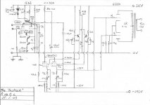
The "Instock" Amplifier
I have settled for 6k a-a; this seems to give the best compromise between higher order distortion and THD - 8k was worse for higher orders.
Here's the diagram; sorry about the quality - life's too short to learn drawing packages.
Briefly, the 50 ohm pot at the bottom of the 13D3 allows me to balance the valve sections at DC. As can be seen, the (red) LED is biased from the HT supply via the 130k resistor. The bias voltage (4V) is high enough to ensure that there are no problems when driven hard.
Turning to the D3A pentode cathode followers, g2s are supplied via the emitter followers (they are MPSA42s). The base voltage is supplied by the potential dividers; the lower halves of these are bypassed with the 0.47uF caps; these fit the little board and anyway give a -3dB point of about 3.5Hz. The 20 ohm pots provide bias adjustment for the output stage.
The amplifier will deliver over 15W, with an input of +7dB (1.7v rms) but distortion is quite high at these levels; personally, I blame the output transformer which is very old and probably wasn't very good when it was new. I am delighted at the very low levels of high order (4th and above) harmonics. And it does sound really very good.
I have not drawn the power supply - easier to describe it.
A Tektronix transformer provides via two bridges, +325V and -253V. On the +ve side there are a 4uF input cap, a 20H choke and a 220uF cap. On the -ve side, a 68uF cap a 270 ohm resistor and a 220uF cap. As this is supposed to be experimental, I have not employed the usual refinements: bypassed diodes, RF chokes on the mains etc. However it is very quiet.
7N7
Attachments
Paul,
Looks very interesting. Not something for "valve only" people for sure!
The only "silly"I can spot presently is the 1n4148, which appears to be reversed.
I really like the cathode followers DC coupled to the output valves.
Two months ago, when I suggested such a thing was a good idea, I was howled upon, and even pressed by 1 venerable member and 2 moderators (1 now defunct) to withdraw my comments. Apparently "all" cathode followers are "rubbish".
But I don't think so.
Cheers,
Looks very interesting. Not something for "valve only" people for sure!
The only "silly"I can spot presently is the 1n4148, which appears to be reversed.
I really like the cathode followers DC coupled to the output valves.
Two months ago, when I suggested such a thing was a good idea, I was howled upon, and even pressed by 1 venerable member and 2 moderators (1 now defunct) to withdraw my comments.
Apparently "all" cathode followers are "rubbish". But I don't think so.
Cheers,
- Home
- Amplifiers
- Tubes / Valves
- More 6158/13D3