PUB TALK.
Hi,
Thought you was...
Doesn't really matter though...you catch my drift.")
If you allow a litle tip:
Never make gridstoppers any larger than strictly necessary.
Ciao,
Hi,
Thought you was...
I meant to try reducing the value of the grid stoppers,
Doesn't really matter though...you catch my drift.
If you allow a litle tip:
Never make gridstoppers any larger than strictly necessary.
Ciao,


Re: PUB TALK.
Of course and this is particularly apposite in this case, where I am anxious to have as low a source resistance as possible. However, I once built a 6SN7 line stage with cathode followers. The 6SN7s had 470 ohm grid stoppers - a typical choice - but the stage was oscillating at about 2.5MHz!
On the 6528A I have used the minimum recommended by the makers (1k) which is pretty low for an output stage - even EL84 uses 4.7k as a rule.
However, I am going to try 470 ohms and watch the 'scope!
Incidentally, I am considering using a similar arrangement of driver stage in the 13E1 amplifier. Here though bias is about
-51V, so I shall have to wring some more swing out of it
7N7
fdegrove said:Hi,
Thought you was...
Doesn't really matter though...you catch my drift.
If you allow a litle tip:
Never make gridstoppers any larger than strictly necessary.
Ciao,
Of course and this is particularly apposite in this case, where I am anxious to have as low a source resistance as possible. However, I once built a 6SN7 line stage with cathode followers. The 6SN7s had 470 ohm grid stoppers - a typical choice - but the stage was oscillating at about 2.5MHz!
On the 6528A I have used the minimum recommended by the makers (1k) which is pretty low for an output stage - even EL84 uses 4.7k as a rule.
However, I am going to try 470 ohms and watch the 'scope!
Incidentally, I am considering using a similar arrangement of driver stage in the 13E1 amplifier. Here though bias is about
-51V, so I shall have to wring some more swing out of it
7N7
CRITTERS.
Hi,
Mainly RFI osc.
The 6C45C is another matter,it tends to go into self osc.
Chin kampai,
Hi,
I'm not clear on these gridstoppers.
Mainly RFI osc.
The 6C45C is another matter,it tends to go into self osc.
Chin kampai,
Re: THE SHORT ANSWER.
Design oscillators?
Perish the thort in the words of N. Molesworth.
I shall try to reduce the value of them for the reasons I gave above - and I shall be keeping a close eye on the 'scope.
When I've fixed the 13E1 amp I'll have a go and also try removing the grid leaks. I'll report my findings, gentlemen, for your perusal
7N7
fdegrove said:Hi,
Although this was voiced by me before...
Don't design oscillators, gridstoppers as any other series R will eat microdetail and as such will reduce dynamic resolution.
I think this should make sense?
Cheers,
\Frank,the unipivot.
Design oscillators?
Perish the thort in the words of N. Molesworth.
I shall try to reduce the value of them for the reasons I gave above - and I shall be keeping a close eye on the 'scope.
When I've fixed the 13E1 amp I'll have a go and also try removing the grid leaks. I'll report my findings, gentlemen, for your perusal
7N7
Attachments
WRONG POST WRONG PLACE...
Hi,
This should have gone into the 6C45 thread...blimey...reducing Rg won't hurt though.
Sorry,wrong channel...
Back to the bunker...
Hi,
The 6C45C is another matter,it tends to go into self osc.
This should have gone into the 6C45 thread...blimey...reducing Rg won't hurt though.
Sorry,wrong channel...
Back to the bunker...
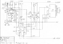
For some reason the link in blue above didn't work so here's the schematic in question.
It looks like the DC difference between G2 and cathode of approx. Vbe is maintained and that they will also track at AC.
Does anybody have experience with or knowledge of this Pentode CF circuit?
Thanks
It looks like the DC difference between G2 and cathode of approx. Vbe is maintained and that they will also track at AC.
Does anybody have experience with or knowledge of this Pentode CF circuit?
Thanks
Attachments
- Home
- Amplifiers
- Tubes / Valves
- More 6158/13D3