Hi Giaime,
I think V3 needs to be reversed - as drawn it shows a positive bias on the gate of M1.
Also while I understand the purpose of R21, and R22, I suspect the R1 cathode resistor would provide sufficient current limiting in the event of a tube failure. Those two resistors do two things:
* They reduce the effective load impedance on that ECC88 to just 50K.
* They reduce the PSRR of the first stage to under 30dB if my math isn't slightly off.
Should you want to keep these I would increase them to about 1M ohm - they won't normally be doing anything and the amplifier will not be on for too long if the ECC88 is bad anyway. This change will address both issues with varying degrees of effectiveness.
Also I think 720V on the plate of a 5687 is a little risky and if a single tube is used you will be far outside of the allowable filament/cathode voltage differential. IMO Something more like 400V ought to provide enough swing.
Also the 5687 as a mu follower can be configured to drive an 845 without the intervening mosfet buffer if run at reasonably high currents. For great linearity these really like to run at 10mA or more despite what the model might predict. Just watch that you don't exceed the individual and combined dissipation limits whatever operating point is chosen..
Also a grid stopper of 27K seems excessive to me, a 1K right at the grid ought to be sufficient to prevent oscillation. If you are trying to reduce bandwidth IMO the best and most consistent way is with a deliberate lpf somewhere in the path.
One other thought from experience I have found that the 211/845 can oscillate depending on layout if there is not a small grid stopper resistor near the grid, 1K is usually enough. (I'm a big fan of grid stoppers..)
Edit added a few extra thoughts and corrected a grammatical error or two...
Hello Kevin,
you moved good points. First I have to say that I optimized the circuit in the simulator, not in real life, so I was really looking for distortion numbers.
V3 IS reversed, if you zoom, you'll see that near it there's "-133" not "133". However I agree, bad practice. I'll reverse and put 133V.
R21 and R22... aside for "safety" reasons, I understand very well your comments and I surely would have made them 1M in real life. But you know what? I get less distortion this way. I think that's for 2 reasons that I have to examinate:
1) harmonic cancellation with the following stage: increasing ECC88 distortion might decrease total distortion.
2) a totem pole likes to have a fixed and not-so-high load.
We're talking about differences of 0.1%, but they exist. I will re-verify in the simulator, however.
About the 720V, they are really 620V instead if one chooses AC coupling between the first two stages. With DC coupling, I need more volts, and of course in a desing like this heater-cathode potential IS an issue, but can be easily resolved by using one 5687 for the upper triode in both channels and bias the heaters at something like 400V.
And NO, I can't get the needed 160Vrms swing with 400V B+.
The mosfet is there because that's easier for them to DC couple to a trasmitting triode grid, and to allow considerable 845 A2 operation (we're talking 33W from a single tube!). A 5687 mu follower would distort too much.
The 27k grid stopper of course isn't a grid stopper: why one would so drastically limit bandwidth? And good practice says to limit bandwidth in the first stage, not in the second. Even this time, like the 100k resistor, 27k gave much lower distortion than none at all, it's limiting 5687 grid current on peaks.
As I already said, that's not a "real" design now, so I can't predict if the 845 will oscillate. Surely I would cure it not with a grid resistor (that will ruin all my A2 attempts) but with grid and/or plate RF chokes.
I appreciate much your experienced comments!! Thank you!
")
you moved good points. First I have to say that I optimized the circuit in the simulator, not in real life, so I was really looking for distortion numbers.
V3 IS reversed, if you zoom, you'll see that near it there's "-133" not "133". However I agree, bad practice. I'll reverse and put 133V.
R21 and R22... aside for "safety" reasons, I understand very well your comments and I surely would have made them 1M in real life. But you know what? I get less distortion this way. I think that's for 2 reasons that I have to examinate:
1) harmonic cancellation with the following stage: increasing ECC88 distortion might decrease total distortion.
2) a totem pole likes to have a fixed and not-so-high load.
We're talking about differences of 0.1%, but they exist. I will re-verify in the simulator, however.
About the 720V, they are really 620V instead if one chooses AC coupling between the first two stages. With DC coupling, I need more volts, and of course in a desing like this heater-cathode potential IS an issue, but can be easily resolved by using one 5687 for the upper triode in both channels and bias the heaters at something like 400V.
And NO, I can't get the needed 160Vrms swing with 400V B+.
The mosfet is there because that's easier for them to DC couple to a trasmitting triode grid, and to allow considerable 845 A2 operation (we're talking 33W from a single tube!). A 5687 mu follower would distort too much.
The 27k grid stopper of course isn't a grid stopper: why one would so drastically limit bandwidth? And good practice says to limit bandwidth in the first stage, not in the second. Even this time, like the 100k resistor, 27k gave much lower distortion than none at all, it's limiting 5687 grid current on peaks.
As I already said, that's not a "real" design now, so I can't predict if the 845 will oscillate. Surely I would cure it not with a grid resistor (that will ruin all my A2 attempts) but with grid and/or plate RF chokes.
I appreciate much your experienced comments!! Thank you!
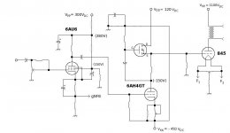
I also have a preliminary design for an 845 amp as well.
Here's the proposed Q-Point:
Q-Point (845):
Vpp= 1100Vdc
Ipq= 70mA (80 -- 110mA also possible, even if it busts the specs by a small margin)
Zl= 10K
Vi= 225Vp
Vgk= -175Vdc
With a estimated gains of 80 (6AU6) and 7 (6AH4GT) there is sufficient gain margin for gNFB. Given the operating conditions, there is a Hammond OPT that will work just great for this. Loadlines for the 6AU6 preamp and the Kimmel are both looking very good, so far as estimated THD is concerned. Since the 6AU6 is going to have to swing an unusually wide margin, the screen voltage is regulated with a rather stiff voltage divider to insure the most linear performance here. (May update this to a SS regulator.)
Including a hybrid Kimmel will ensure enough grid drive to push the 845 into Class A2, make for better transient overdrive behaviour, and be able to charge the input + Miller + stray capacitance for good slew rate at the upper end of the audio band.
Attachments
Standard OTS 800VCT @ >250mA Hammond (or any other brand) power transformers will give you more than 1KV if you use them with a bridge rectifier whether hybrid, all tube or SS. The center tap will also provide you with 1/2 the overall voltage which with a little additional filtering may do nicely for most driver stage topologies.
Take a look at old ARRL Handbooks under powersupplies to get a general idea.
Plenty of surplus transformers on eBay and at ham fests where they still occur..
Take a look at old ARRL Handbooks under powersupplies to get a general idea.
Plenty of surplus transformers on eBay and at ham fests where they still occur..
It is hard to guess what either of these designs will sound like without building them. I think that they both can be made to work with a little tweaking.
Giaime:
I have limited experience with SRPP circuits, even though I used one in my 300Beast amp. I haven't done much with them since. I do have reservations about putting 720 volts on a 9 pin socket, especially if it has any metal in it other than the pins, or is mounted to a metal chassis. 160 volts RMS (about 450 P-P) does REQUIRE a lot of supply voltage. My amp uses a CCS loaded 45 with a supply voltage of 500 volts and it is the limiting factor in the amps output power. Unfortunately neither the 45 or the CCS could take any more voltage. The 845 is the only tube that requires this much drive the 211 and the 833A can be driven with less voltage.
kevinkr:
I haven't measured the peak grid current with the 845. I did measure it (using a scope in differential mode across a 10 ohm grid resistor) on the 833A experiments. The peak grid current was over 100mA! Lets say that the 845 can draw 10 to 20 mA on positive peaks. A 5687 will have a hard time doing this. I tried a bunch of cathode followers (and other circuits) before discovering the mosfet follower. Which CF worked the best. A big sweep tube. I was using a 6LW6, but I think that a smaller one (like the 6AV5) would work to drive an 845.
Miles Prower:
I like simple circuits. This one looks too simple. Please keep us posted if you build it.
All:
The power supply is critical in any SE amp. The supply for this amp is a lot more critical than I originally thought. When I built the amp I was using the power supply from the "Poor Man's Ongaku" with the Audio Note transformer. This one had poor regulation and coupling from the 450 volt suply to the 960 volt supply. I also wanted more voltage.
My current power supply uses my favorite Allied 6K7VG for +490 volts (with a 5AR4) and - 400 volts (SS rect - choke input). I use a 480 volt industrial transformer feeding a voltage doubler made with 5AR4's to get 1100 volts. A bridge rectifier (SS) across an isolation transformer frovides the +150 volts. All filament voltages are DC. I built this power supply for about $150. I thought that is was great........until.
I had a monster ferro resonant 1500 volt 1/2 amp 100 pound power supply in here for the 833A experiments. I decided to unhook the input capacitor in this supply to lower its voltage (still 1300) and hook it up in place of the HV section of my 845 power supply. It made my power supply sound anemic. Maybe it was just the extra voltage. The ferro resonant transformer makes a rude buzzing sound that makes it useless for audio.
I have the itch to build another HV power supply for the 845. I don't have time yet, but I have been collecting HV transformers from Ebay. I am thinking 1600 to 2000 volt CT (I now have a few to try) transformer feeding a pair of 3B28 Xenon rectifiers (top secret drop in replacement for 866A'a - no mercury). A bank of motor run caps instead of electrolytics.
tubelab.com said:
Miles Prower:
I like simple circuits. This one looks too simple. Please keep us posted if you build it.
Yeah, me too. And I do intend to build it since I already have the 845s. Got a helluvadeal on Chinese 845s at the Dayton Hamvention: two/$30.00. As for power, that'll be from an ICT with fullwave doubler driving an active regulator for plate power to the 845s. I'll need a separate SS plus/minus supply for the front end.
Not a question of "if", but "when".
Not a question of "if", but "when".
I have a lot of projects like this.
for me, its how....how much!
Those are always Sherris words. Usually followed by "How many amplifiers do you need? You can only listen to one at a time."
Hey, I sell the ones that I don't like. The problem is that there haven't been any of those in a while.
Giaime said:Much could be improved in my design, but I'd like to get more linear stages with no feedback. I'll see...
I'm all for having the best possible linearity on all stages as well, and the hybrid Kimmel certainly qualifies on that count. However, I most certainly do not buy into the BS that feedback is a bad thing. There is no such thing as a perfectly linear stage, and every OPT (except an air core) has its own nonlinearities. They're unavoidable. So why not take an inherently good design and make it better with gNFB error correction? Do the initial design right, and you won't be needing much anyway.
Now, the 845, with an r(p) of 1K7 ain't half bad so far as Zo and speaker damping. However, why not get that Zo down a bit and improve the damping by adding some gNFB? Isn't poor bass performance a big complaint about SETs (or even hollow state amps in general for that matter)? Why just settle for what you get as opposed to applying a very simple, but very effective, enhancement?
What about all those complaints that 300Bs sound "too colored"? Aren't these all zero feedback designs? Hmmmm.....
gNFB in a SET may be considered "heresey", well t'hellwiddat. Call me a heretic. Then come over for a listen, then we'll talk about it.
An externally hosted image should be here but it was not working when we last tested it.
Hi Miles,
no belief in nfb BS neither from me. I'm an engineer, remember
Just wanted to get the best possible linearity before thinking of feedback. I have to choose the good topologies: this is one of the possible combination. I will experiment with a pentode + triode with Kimmel.
no belief in nfb BS neither from me. I'm an engineer, remember
Just wanted to get the best possible linearity before thinking of feedback. I have to choose the good topologies: this is one of the possible combination. I will experiment with a pentode + triode with Kimmel.
HA! I am an engineer too, and I don't like the results of global/loop NFB. There are other ways of getting a bit of FB that doesn't have such an effect on the percieved sonics.
Also cconsider higher voltage MOSFET's. Fairchild's FQP-series are available up to 900V and have a +/- 30V gate-source tolerance. If there's some particular reason to use the IRF820, consider protecting the gate with a low-leakage/low impedance Zener.
cheers,
Douglas
Also cconsider higher voltage MOSFET's. Fairchild's FQP-series are available up to 900V and have a +/- 30V gate-source tolerance. If there's some particular reason to use the IRF820, consider protecting the gate with a low-leakage/low impedance Zener.
cheers,
Douglas
I am engineer too!  And I use gobs of feedback to get the accuracy required for the ATE instruments I design - in audio I generally eschew the use of global feedback and these days I even use local current feedback pretty sparingly. Global feedback really seems to "kill" the sound, it measures better, it just doesn't seem to serve the music...
Long ago when I was working on my ill-fated otl design (I discovered "the joy of SE" about then ) I discovered to my consternation that my circlotron design sounded much better with the global feedback connections removed - and this with a calculated source impedance of at least 6 ohms! The sound just opened up, detail became more evident, yada yada yada... It measured pretty ok too actually.. Other problems killed it off unfortunately - not the least of which was the massive amount of heat generated by six 6C33 per channel, and the frightening lack of efficiency. (You should have seen that utility wattmeter spin... LOL)
And I use gobs of feedback to get the accuracy required for the ATE instruments I design - in audio I generally eschew the use of global feedback and these days I even use local current feedback pretty sparingly. Global feedback really seems to "kill" the sound, it measures better, it just doesn't seem to serve the music... Long ago when I was working on my ill-fated otl design (I discovered "the joy of SE" about then
) I discovered to my consternation that my circlotron design sounded much better with the global feedback connections removed - and this with a calculated source impedance of at least 6 ohms! The sound just opened up, detail became more evident, yada yada yada... It measured pretty ok too actually.. Other problems killed it off unfortunately - not the least of which was the massive amount of heat generated by six 6C33 per channel, and the frightening lack of efficiency. (You should have seen that utility wattmeter spin... LOL)Brian Beck said:I'm an engineer too, and my view on NFB is...it depends!
...becoming an audio politician
It does depend on a lot of things. Personal taste among them...
I build with FB, I just avoid the loop/global method. One can do quite a job without it. It required a new circuit, but that's OK...there are still new tube circuits to be developed every now and then...
If I were worried about efficiency, I would certainly avoid Class A tube circuits. Sometimes a 1kW heater is a good thing!
cheers,
Douglas
 ).
).
If an amp is designed correctly most of the non linearities will be in the output stage (the tube and the OPT). So why do you need to wrap feedback around the whole amp just to fix up the output stage.
I have been playing with cathode feedback for tha last few months and find that I have to really overdo it before it messes up the sound. I have found that about 3 db of CFB can improve dynamics and transients while lowering the distortion and improving frequency response. It does wonders for low cost OPT's like the 125CSE and the $18 Edcor.
I think that it would be a tough deal for the 845 though. My 845 amp is under 1% at 10 watts and that is almost all 2nd harmonic, so I don't need feedback on it.
- Status
- This old topic is closed. If you want to reopen this topic, contact a moderator using the "Report Post" button.
- Home
- More Vendors...
- Tubelab
- Especially for Tubelab: 845 amp 2.0