George's tubelab looked like a good idea to me.
http://www.tubelab.com/The_Tubelab.htm
I went to Home Depot, and they didn't have the nylon pegboard. Bummer.
Anyone else try this?
http://www.tubelab.com/The_Tubelab.htm
I went to Home Depot, and they didn't have the nylon pegboard. Bummer.
Anyone else try this?
I did find this as the cheapest place to get nylon pegboard. They shipped pretty quickly.
http://www.chdist.com/
SKU 1538300 Poly Duraboard
http://www.chdist.com/
SKU 1538300 Poly Duraboard
I dug around the lab and found a piece of the material that had part of the label on it. It contained the leters EverT.....
Some Googleing led to this article:
http://www.the-review.com/archive/09172004/PDF/D10.pdf
and this:
http://www.helpwantedredding.com/currents/home_garden/past/20041001handg351.shtml
I guess that my memory isn't what it used to be. It comes from Loews, not Home Depot. At least here the two stores are about 1 block apart. I often go to both on the same trip. It is cheap, $11 for a 2 by 4 foot piece.
This is another pegboard prototyping technique. Mine uses a 24”x24” Masonite pegboard mounted on 1.5”x1.5” strips of wood around the perimeter to hold the board off the table. Now that I’ve heard of the Nylon pegboard material, I will try that. I just place Teflon-insulated standoffs into a peg hole where I need a node and tack-solder the parts’ leads to them. I like to tack-solder because it’s quick and I feel that I can get a reasonably secure and reliable connection. Using fairly long leads the parts can be used again in the final version. I do like Tubelab’s breadboard approaches too.
Attachments
Most of you guys are way ahead of me on the proto-board scene.
I'm embarrassed to admit mine is a plain old plank of wood with a bunch of sockets attached. Connection points are long screws through the board with nuts and washers on top and insulated on the bottom. It's prone to vhf oscillations with certain tubes depending on wire lead dress, and its probably a death trap. I haven't used it much in the last 10 yrs..
I design and build things and they usually work well, little additional tweaking has been required, but I can't help but feel that I am missing the opportunity and some fun in being able to quickly check things out. And when things don't work quite as anticipated what a pain...
I'm inspired and shamed at the same time.. I'm going to do something quite similar to what George (tubelab) came up with. It will probably make the hobby a whole lot more fun too.
I'm embarrassed to admit mine is a plain old plank of wood with a bunch of sockets attached. Connection points are long screws through the board with nuts and washers on top and insulated on the bottom. It's prone to vhf oscillations with certain tubes depending on wire lead dress, and its probably a death trap.
I haven't used it much in the last 10 yrs..I design and build things and they usually work well, little additional tweaking has been required, but I can't help but feel that I am missing the opportunity and some fun in being able to quickly check things out.
And when things don't work quite as anticipated what a pain... I'm inspired and shamed at the same time.. I'm going to do something quite similar to what George (tubelab) came up with. It will probably make the hobby a whole lot more fun too.
Jeb-D. said:I'm all about the euro barrier strips
I bought a bunch of 6 section Molex ones from Mouser. Attach to the modules with 4-40 screws.
I bought 26" picture frame pieces from the local girlie arts & crafts place. About $1 per side. Cut 2'x2' of the peg board, and screwed it in. Stable enough.
You need pvc covered for hookup wire. It is very hard to get slippery teflon stuff into the euro block holes. Frayed leads are a pain too, so I have been tinning a few.
See George's site:
http://www.tubelab.com/The_Tubelab.htm
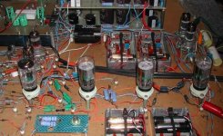
Scroll to the bottom for tubelab 3. That's what I am trying to copy.
Here is a bad camera pick of mine, kinda sorta.
http://www.tubelab.com/The_Tubelab.htm
Scroll to the bottom for tubelab 3. That's what I am trying to copy.
Here is a bad camera pick of mine, kinda sorta.
Attachments
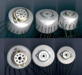
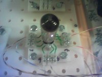
Here is a closeup of a 9 pin module. I can't see and I am sometimes stupid, so I numbered the connectors.
My pegboard has 3/8" holes, so I use 3/8" bolts in the corner of each module. Reasonably stable, mechanically.
For 8 pin, I cheated for now and just used relay sockets with screw posts.
My pegboard has 3/8" holes, so I use 3/8" bolts in the corner of each module. Reasonably stable, mechanically.
For 8 pin, I cheated for now and just used relay sockets with screw posts.
Attachments
A few questions.
George,
I'm glad you came up with the info on the plastic pegboard. I'd been to 3 Home Depots and just thought the ones in this area (Tampa) weren't carrying it. A trip to Lowe's and it's mine! This getting older stuff really stinks, doesn't it! I can't remember diddly anymore. However, for all of you who are rushing out to your nearest Lowe's, the price has gone up a bit to $12.96 for a 2' x4' sheet. Still a good deal.
How big did you make the base and have you found it to be a good size? Also, what did you cut the stuff with? Most of my experiences with cutting Lexan, Plexiglass, nylon, etc. has been like ethermion; the stuff just melts instead of cutting unless you really slow the saw down.
Also, I would like to say I think the Tubelab 3 idea is trully inspired. It's definitely one of those "Darn, I wish I'd thought of that" ideas.
I can't see and I am sometimes stupid, so I numbered the connectors.
So, I am a blonde and I make dumb mistakes too. If you look closely at mine, the generic ones are numbered too.
I made a few modules that are specific to a particular family. The 9 pin modules visible in the pictures are made for a 12A_7 tube. It also works with the 6BQ7 and 6BK7 and a few others. They are lettered "K" "G" "P" and "F" and they have 220 ohm grid stoppers mounted right at the sockets.
I also have some octal modules thet are specific to the 6S_7, 6AS7, 6EM7 (and others) tube types. The octal module in the picture is a generic dual octal module that was created with push pull in mind. I also have a dual octal module made for 6L6, EL-34 and KT-88 tubes. It has screen and control grid stoppers on it, and the screen grid is wired to both the left and right side of the module, so it could be used for UL (on the right, next to the plate) or wired to a regulator (on the left side).
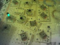
There are also component modules with only 2 or 4 euro barrier strips on them. They are used for the capacitors and resistors.
There is a strip of the euro barrier connectors along the rear of the wood frame for all of the power supply connections. They are pre wired to dual bannana jacks and marked "GROUND" "FIL A" "FIL B" "B+ 1" "B+ 2" and "BIAS".
I can add some more pictures to the web page this weekend.
I am at work now, so I can't look right now, but I believe it was 18 inches by 24 inches. Looking at the picture, that looks about right if the holes are spaced on 1 inch centers. The size was dictated by the available bench space.
I cut it with a circular saw which has a rather dull blade that was made for cutting plywood. Again I can't look now to see the number of teeth. I laid the plastic on a sheet of plywood so that the edge to be cut off is hanging over the edge of the wood. You can mark the plastic with a ball point pen. The marks will not come off later though.
I had made two other "Tubelabs" before this one. I was in Home Depot (OK Loews) one day and I saw the plastic pegboard, and I knew that I could make something cool with it, I just didn't know what. I bought one. It sat around for several months before the idea happened. I canabalized Tubelab 2 for the wood base, and made Tubelab 3 in one afternoon. The 1/4 - 20 bolts and nuts were left over from another project.
Thanks George,
Available bench space, huh. I understand about that. I have a reasonably sized bench but it seems like part of it is always covered with "residue" from umpteen other projects. 18"x24" will leave plenty of board left over for the movable modules.
I have several plywood circular saw blades in various states of dullness from cutting melamene faced particule board shelves and supports for a couple of hamshacks so I should be able to find one which will work. Also, thanks for the great tips in the post a couple before this one.
Once again, it's a great idea
Stay safe this hurricane season.
Ken
George,
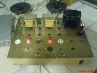
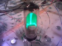
This is coming together for me. I really, really, like the idea. I wired up a magic eye tube in minutes. No solder! Very cool. I was 1/2 way into an Aikido stage before the wife came home...
Anyway, I have a question about test points. The euro blocks do not lend themselves to probes, and all my wire (module & hookup) is sleeved up to the connections. Any thoughts about providing space for probes to clip on?
Attachments
Any thoughts about providing space for probes to clip on?
I have a bare copper wire across the back of a euro barrier strip that ties all of the terminals together. That strip is the "single point ground" for all of the experiments. It is also a convenient point to attach the ground connections for meters and scope probes.
For probing around in a live circuit, just touch the probe to the setscrew in the barrier strip. For more permanent connections, I have been using mini - grabbers or aligator clips on the component leads or the tube socket pins.
If you want something more stable, you could make up a module with pin jacks. They could be wired into the circuit like components. Most meter leads fit into them.
- Status
- This old topic is closed. If you want to reopen this topic, contact a moderator using the "Report Post" button.
- Home
- More Vendors...
- Tubelab
- tubelab