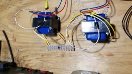
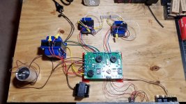
Hi I am getting ready to test my SSE build on a breadboard of sorts, thing is I do not have proper speaker terminals yet. I was going to use mains rated plastic terminal strips to connect speakers, but I'm unsure if they need to be grounded as George has them in his wiring diagrams.
I configured the board for nearly the simplest configuration, triode mode no CFB, it does have a choke and a supplemental cap. I intend to try it out like that before adding all the bells and wistles such as switches for ultralinear, rectifier, and cfb. I have all the switches volume and rca inputs on a metal plate so everything is grounded and will run grounds for choke and transformers to iec but im not sure if I need to run a ground from the plastic terminal strips for the speakers.
I configured the board for nearly the simplest configuration, triode mode no CFB, it does have a choke and a supplemental cap. I intend to try it out like that before adding all the bells and wistles such as switches for ultralinear, rectifier, and cfb. I have all the switches volume and rca inputs on a metal plate so everything is grounded and will run grounds for choke and transformers to iec but im not sure if I need to run a ground from the plastic terminal strips for the speakers.
This is so frustrating because there is not a lot of info on installing binding posts in an amp! When I Google it I get tons of "how to hook up speaker to your amp" but nothing on wiring posts into an amp.
According to George's wiring diagram the ground is tied into one of the two wires from the opt I'm assuming the common wire? Then attached to the post?
As stupid as this may seem I have never wired a speaker terminal/post before and have no clue. I just got my posts in the mail and it seems the metal post is isolated from whatever your case is made from by rubber washers? True? Ah! It was easier to solder the entire project! Someone help!? Please? Lol
This is so frustrating because there is not a lot of info on installing binding posts in an amp! When I Google it I get tons of "how to hook up speaker to your amp" but nothing on wiring posts into an amp.
According to George's wiring diagram the ground is tied into one of the two wires from the opt I'm assuming the common wire? Then attached to the post?
As stupid as this may seem I have never wired a speaker terminal/post before and have no clue. I just got my posts in the mail and it seems the metal post is isolated from whatever your case is made from by rubber washers? True? Ah! It was easier to solder the entire project! Someone help!? Please? Lol
Yes its the common wire.
Sometimes the live speaker wire is used as a feedback connection too.
I don't know without a circuit diagram.
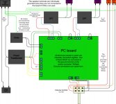
The different options here, so if 8th diagram down is your configuration, then, yes, ground the common speaker wire Wiring Diagrams | Tubelab
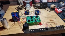
I'm not sure I understand what your question is, but for testing a breadboard amp, I would just get a handful of wire nuts and use those to connect the OPT secondary leads to the speaker wires for your TEST speakers.
Even clip leads would work.
Win W5JAG
This is a tubelab see board and according to the wiring diagram there is a ground to from the speaker posts. At least for the configuration it is currently in. I just want to be certain I'm reading it correctly.
I didn't think you are supposed to ground the coil of a transformer but that is what it appears to be telling me. Am I wrong? Lol
Attachments
The different options here, so if 8th diagram down is your configuration, then, yes, ground the common speaker wire Wiring Diagrams | Tubelab
Yes that is the one I am using, thank you! I just want to make sure I was getting it right.
The common side of the OPT secondary is grounded mainly for safety reasons. It also used for Cathode Feedback (CFB).
Although very uncommon, it is possible for an OPT to develop a short, primary to secondary and still pass audio in the normal fashion. This will put B+ voltage on your speaker wires and could fry an unsuspecting user. Grounding one side of the OPT secondary will cause the amp's fuse to blow if this did occur. I have seen one such shorted OPT in my 50 + years of messing with tube amps. It was in a Fender Bandmaster, and caused the fuse to blow, after taking out the power supply diodes.
The live (not common) speaker wire on the OPT is used for CFB if this option is used.
The common side of the OPT MUST be grounded if CFB is used, or the feedback will not work. There are some "audiophools" out there who claim the the amp sounds better if the secondary is left floating. It is possible that a floating secondary would present a few pF less capacitance, so in theory a difference could be measured with a really wimpy tube or a lousy OPT. I prefer to always ground the OPT for safety and noise pickup / radiation issues on the speaker leads.
Temporary testing can be done without the ground but CFB will not work.
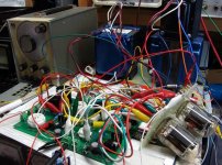
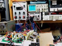
Who would do such a thing........Almost anything could be done if you have enough clip leads.......even, try some different tubes in an SSE.....which led to a new SE PC board.....and more clip leads!
You can even use those plastic "euro strips" to build an entire amp too.
Although very uncommon, it is possible for an OPT to develop a short, primary to secondary and still pass audio in the normal fashion. This will put B+ voltage on your speaker wires and could fry an unsuspecting user. Grounding one side of the OPT secondary will cause the amp's fuse to blow if this did occur. I have seen one such shorted OPT in my 50 + years of messing with tube amps. It was in a Fender Bandmaster, and caused the fuse to blow, after taking out the power supply diodes.
Sometimes the live speaker wire is used as a feedback connection too.
The live (not common) speaker wire on the OPT is used for CFB if this option is used.
I didn't think you are supposed to ground the coil of a transformer
The common side of the OPT MUST be grounded if CFB is used, or the feedback will not work. There are some "audiophools" out there who claim the the amp sounds better if the secondary is left floating. It is possible that a floating secondary would present a few pF less capacitance, so in theory a difference could be measured with a really wimpy tube or a lousy OPT. I prefer to always ground the OPT for safety and noise pickup / radiation issues on the speaker leads.
Temporary testing can be done without the ground but CFB will not work.
Even clip leads would work.
Who would do such a thing........Almost anything could be done if you have enough clip leads.......even, try some different tubes in an SSE.....which led to a new SE PC board.....and more clip leads!
You can even use those plastic "euro strips" to build an entire amp too.
Attachments
- Status
- This old topic is closed. If you want to reopen this topic, contact a moderator using the "Report Post" button.
- Home
- More Vendors...
- Tubelab
- Speaker terminal question