I am looking forward to finish my SE 45 building. I hope there is enough power... my speakers are 92 db efficiency. The output transformers are from the swedish LUNDAHL LL1620 60mA. I think this have also an influence off the output power. In the speaker cross-over I have connected a RLC element (resistor,coil,capacitor)
I Have read about speaker load (impedance) and valve amplifier but Is there somebody out there who have experience with it and can give me feedback about this issue on a Tubelab TSE with 2-way crossover/speakers in 8 ohm ?
Let me explain:
Let´s assume you have a loudspeaker with 8 ohm, having its max impedance of 16 ohm at 1000 Hz. The impedance rise is of no importance when a conventional amplifier is being used.
However, if you connect this speaker to a valve amp. then this impedance rise leads to an excessive level at 1kHz. Therefore, this impedance riseshould be compensated for in the crossover.
To achive this a RLC element should be connected in parallel to the crossover. The component values are calculated by entering the following data:
the nominel impedance of the loudspeaker ( 8 ohm)
The increased impedance that needs to be corrected (16 ohm)
The frequency where the maximun impedance occurs (1000 Hz)
The neighbouring frequency where the impedance drops - exactly to half its value (12 ohm)
impedanc correction for a valve amp.
R in ohm 16
L in mH 1,62
C in uF 15,63
note: R= sum of resistance- value and resistence of coil.
RLC serial Resornant Circuit Calculator.
Strassacker: Speaker Building, Components
Michael
thanks for the interesting feedback with method to test this issue. I have done it this way on my Tubelab SSE that I finish last year and the 2-way 8 ohm speaker. and I will do the test to my tubelab SE once I am finish with it
The result at two levels (0-100) is:
level 32
1,1V at 200hz and 1,5V at 1000hz (1,0V at 44hz) used ear protector at this level
level 24
0,6V 200hz and 0,8V at 1000hz
The result of right and left side are between 0,1V
The V is about 1/3 less at low freq.hz Is this normal ?
can I conclude of this test, That the power is about the half at 200hz ?
1,1x1,1=1,21/8 = 0,15 (200hz)
1,5x1,5=2,25/8=0,28 (1000hz)
Last edited:
EDITED sorry this is the right result of the test.
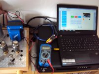
The result at two levels (0-100) tonegenerator sinus 200 and 1000hz measure VAC multimeter (200vac)
level 32
11V at 200hz and 15V at 1000hz (10V at 44hz) used ear protector at this level
level 24
6V 200hz and 8V at 1000hz
The result of right and left side are between 1V
can I conclude of this test, That the power increase at 1000hz to compensate for the impedance rise to 16 ohm at 1000hz
Please give me feedback about you`r experience for this issue
11x11=121/8 = 15,1 (200hz)
15x15=225/8=28,1 (1000hz)
15x15=225/16=14,1 (1000hz)
Attachments
Last edited:
- Status
- This old topic is closed. If you want to reopen this topic, contact a moderator using the "Report Post" button.