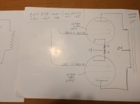
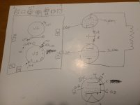
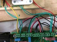
Jacques Here are a few drawings I made to help me at the workbench. The pinout of my tubes is different then yours. Also a photo of the UDB hooked up. The board is viewed from the bottom. Maybe they will be of help
Evan
Evan
Attachments
Do I need to hook anything up to H3 on the UDC board?
H3 is wired to pin 9 on the tubes. It is normally used when running 12 volt tubes like 12AX7's and 12AU7's from a 6.3 volt transformer. The data sheet shows pin 9 unused on a 6CG7 and connected to a shield that runs between the plates on a 6FQ7. I have however seen more violations of this convention that adherence, and plenty of tubes wearing both numbers, with or without the shield. I would say leave it disconnected unless there is hum or oscillation, then ground it. I leave it open and have never seen any issues, but it could create a feedback path if both tubes have shields (a silver piece of metal between the plates).
DRV2-2 and DRV1-1 will connect to pin 5 of the power tubes.
Yes.
DRV2-1 and DRV1-2 will connect to pins 8 and 1 of the power tubes.
You need a way to measure the current through each tube so that you can set the bias. I put a 1 ohm 2 watt resistor between the DRV2-1 and DRV1-2(ground) terminals on the board and pins 1 and 8. Connect a voltmeter set to the 200 mV scale across this resistor when adjusting the bias. With a 1 ohm resistor mV = mA, set it to about 40 mA for a starting point.
Pin 3 of the power tubes will connect to the output transformer.
Yes.
Pins 2 and 7 to the heater circuits.
Yes.
If I’m running in triode mode I don’t need to hook up the screen?
The screen (pin 4) must always be connected to something, or unpredictable results will happen (usually no power output and no tube current. As with the SSE, I connect the screen to the plate with a 100 ohm 2 watt resistor. One end of the resistor to pin 3, the other end to pin 4.
For testing can I substitute an EL34 for a KT88?
As with the SSE, the EL34, the 6L6GC, the KT88, and the 6550 will all work in this amp. Each tube will require a different bias adjustment, and I would run a bit less current with the EL34 or 6L6GC, maybe 30 to 35 mA depending on how much B+ you have.
Do you have an LTSpice model for the Universal Driver Board please George?
If I have one, it's not on this PC. There are a few other places I can look, but I designed this when I was still learning LT spice (2008), so I might not have done much simulation. I may have something similar that I can change a few parts in.....I'll look on some old hard drives that I have stashed on a shelf.
Well, I finally got my garage, spare room, and den cleaned up enough to get to my Universal PP Driver boards.
I put the box of parts on the workbench in the garage, and started printing out schematics, BOM and pictures, and what happens?
Power outage. Power just came back on.
I took advantage of the power outage by taking a shower and reading by lantern.
So, I hope to get to this in the evenings of the next couple weeks.
I'm going out of town Thursday to go visit friends in SC.
Next weekend I'll be at RAT ROD in Bristol TN, so work will be slow.
First up will be 6P41S PP class AB1.
Another project I have is to build a bias supply. I have to build it to test the UPP Driver Board.
Last edited:
Power outage. Power just came back on.
We had a nasty line of storms move through here about 2 hours ago. The power went off and on several times, then off for almost an hour. It came back about 20 minutes ago.
I went to the Dayton hamfest last Thursday and returned late Saturday night. I sold a Honda Element full of stuff I no longer use. Everything from guitars to test equipment to turntables......I kept the Technics SL-D2 that I bought new in 1978, but sold the Garrard SL95B, a JVC and a Realistic.
Before I went, I sorted through about 2500 used tubes last week to find about 50 Telefunken, Amperex Bugle Boy, Western Electric, and other audiophoolery, that I will never use, and traded them for 614 NOS tubes that I will use........more experiments to come, including an amplifier design that nobody has ever seen yet.....anywhere.....if I can solve this pesky issue where tubes EXPLODE!!!!!!
The exploding tube thing is real, but it was a stupid arithmetic error on my part.......those pesky decimal points have a way of moving. A 24 watt tube REALLY doesn't like dissipating 200+ watts, and that big HP power supply we have WILL blow things in half, including tubes.
If I have one, it's not on this PC. There are a few other places I can look, but I designed this when I was still learning LT spice (2008), so I might not have done much simulation. I may have something similar that I can change a few parts in.....I'll look on some old hard drives that I have stashed on a shelf.
Thanks George. I can reuse some of the Williamson model a built 3 years ago. Trouble is, that was 3 years ago and now I have to learn LTSpice all over again.
Currently trying to find models or sub-circuits for the 10N45 and LN4041s.
LTSpice Model
Here is a pdf of my LTSpice model of a 6550 PP amp using the UDB.
I've put this together based on LTP_driver_board.pdf and the most recent BOM including the notes regarding resistors required for G1 drive.
Is the overall topology correct?
How do I apply global negative feedback?
Notes:
Thanks!
View attachment 6550 amp with UDB.pdf
Here is a pdf of my LTSpice model of a 6550 PP amp using the UDB.
I've put this together based on LTP_driver_board.pdf and the most recent BOM including the notes regarding resistors required for G1 drive.
Is the overall topology correct?
How do I apply global negative feedback?
Notes:
- The current sources (IC1 and IC2) and the zeners (IC3 and IC4) are placeholders until I get the appropriate models or subcircuits.
- I'll be replacing the KT88s with 6550s.
- I used 6GU7s in my Williamson amp. I'll replace them with 6CG7s.
- I need to fix an "unknown potentiometer subcircuit error
Thanks!
View attachment 6550 amp with UDB.pdf
Last edited:
Here is the asc file.
Thanks for this. Can I ask a huge favour to save me a lot of time please? I have potentiometer.sub but could you please zip up your other 3 includes and post or send them?
After a lot of searching I'm unable to find downloads for them.
I have the Ayumi models and I could use those in place of the Koren ones.
I found a TL431.sub on LT Wiki but it seems to be missing a symbol. I can't update the include path and save without losing the symbol references from the schematic.
I see you've replaced the 10M45 with a DN2540 FET. Is that because you were unable to find a subcircuit for the 10M45? I couldn't find one.
I've attached my LTSpice file but it needs more work.
View attachment 6550 amp with UDB.asc
I hope this helps, I'm going out of town for a few days and will be out of contact.
Thanks very much!
I've updated the Includes but still getting the message "Couldn't find symbol(s): tl431".
Last edited:
The first two boards had 10K pots in them. They worked fine. As I was building the next batch I switched to 100K pots and that's what I recommend for future builds.
The LM4041 is specified for use between 60 uA and 10 mA of current. The 120K values of R9 and R11 put between 1 mA and 1.5 mA through the chip with the usual +/- 120 to 160 volts of low B+ and B- supplies. About 24 uA of this current will be stolen by the R10 pot if a 100K pot is used, and 240 uA will be stolen if a 10K pot is used, The grid of V1B should not draw any current, or a uA or two worse case, so the 100K pot was chosen to eliminate another unique part from the BOM. Either should work fine, as should anything in between, but I wouldn't go too far outside those values.
The LM4041 is specified for use between 60 uA and 10 mA of current. The 120K values of R9 and R11 put between 1 mA and 1.5 mA through the chip with the usual +/- 120 to 160 volts of low B+ and B- supplies. About 24 uA of this current will be stolen by the R10 pot if a 100K pot is used, and 240 uA will be stolen if a 10K pot is used, The grid of V1B should not draw any current, or a uA or two worse case, so the 100K pot was chosen to eliminate another unique part from the BOM. Either should work fine, as should anything in between, but I wouldn't go too far outside those values.
The first two boards had 10K pots in them. They worked fine. As I was building the next batch I switched to 100K pots and that's what I recommend for future builds.
...
Thanks for the really thorough explanation George. I've ordered the parts for the boards but I'll be simulating and designing the layout and chassis until I can afford to buy the mains and output transformers. The fun is in the journey.
I hope this helps, I'm going out of town for a few days and will be out of contact.
Hi,
Thanks again for your model. I have it all working despite receiving the following message:
Error on line 5 : m§ic1 n020 n022 n024 n024 dn2540 dn2540
Unknown parameter "dn2540"
Error on line 27 : m§ic2 n021 n023 n025 n025 dn2540 dn2540
Unknown parameter "dn2540"
Any idea what that might be please?
I have models for the 10M45S, LM4041 and NDF04N60Z power MOSFET so I'll see how I go incorporating them.
I'll also remove the resistors not required for G1 drive.
KT88/6550 Schematic
Hi George,
Could you please review the attached schematic and tell me if it all looks OK to you? All the component values are drawn from your most recent BOM.
The OT is just what I used on my last project but it is the only 100W OT that Edcor has.
The V1 and V2 anode voltages are from your post #178.
I have a simulation setup of the UDB part which I'll put in a separate post.
Thanks!
Attachments
UDB for G1 drive Simulation
Attached is my LTSpice simulation for the UDB setup for G1 drive (with thanks to TheGimp).
Frequency response looks great.
Output for 1V input is starting to look a bit distorted.
I had to set R4 to 0.015 to get the recommended 120 on the V1 anodes at which point the anode currents are 6mA.
The balance of the V1 anodes is very sensitive to the setting of R10.
How this might correspond with reality I don't know but that's not the purpose of the sim which is to help me better understand the UDB.
Out of interest I'll run some distortion tests as well.
Attachments
I've been thinking about the +/- Supplies.
I was building up a small PS to use for negative bias when doing breadboarding and decided to make it +/- instead of only negative.
I have a Signal Transformer Co 241-8-120 setting on the shelf and thought it would be adequate.
Runing it FWB CT I get +/- 94V, and after running it through FETs with a zener reference and potentiometer for adjustment I can get +/- 10 to about +/- 85V.
So how much voltage is necessary.
If we are running AB1 and rule out AB2, then only the compliance for the FET Followers is necessary for the positive supply. To keep them happy and Cgs low we need at least 25 - 30 V so any supply over that is wasted heat.
The negative supply has more dammand. It has to supply the bias voltage, plus sufficient headroom to drive the tubes to cutoff. That is approximately twice the bias voltage.
For example, with the 6L6GC at 450V B+, bias is -37V and Peak Af g-g drive is 70V p-p. So, 37 +(70/2) or -71V should suffice. A little headroom is always nice, so the -85V supply should suffice.
Am I missing something?
- Home
- More Vendors...
- Tubelab
- Tubelab Universal Driver Board, 2015 version