So here is my plan for the power supply for a mono blocks. I'll be using a 5AR4 for rectification, 6CG7's for drivers and KT88's for power tubes.
For the tubes I’m thinking of copying the power supply of the SSE and plan to use an Allied 6K7VG I have per the diagram below:
:http://www.diyaudio.com/forums/attac...1&d=1523821605
Would this work ? Are there values I need to change?
I'm assuming the 6.3V taps can go directly to H1 and H2. Correct?
For the mosfets I’m thinking:
http://www.diyaudio.com/forums/attac...1&d=1523823171
With PSUD I get 154 volts for the mosfets.
This is continues to be learning exercise for me.
Thanks for your patience, Jacques
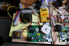
OK, I'm a bit behind on this so I grabbed a hacked up SSE board and wired it's power supply section to the test amp breadboard. I used the same mos power supply that I have been using. I measured +142 volts and - 141 volts on the mos supply, 502 volts at idle on the main B+ and 445 while putting out 65 watts. The tubes in the amp are older Chinese KT88's and the SSE has a Sovtek 5AR4. My line voltage is usually in the 122 to 127 volt range but I didn't measure it today.
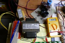
The Allied 6K140HF is Hammond's version of the Triad N-68X, either will work fine. I couldn't find a Triad.
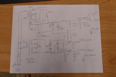
I drew a schematic of what I have here, took a picture of it, and scanned it to PDF.
Note, I really did stick a 4D32 into an SSE......it didn't work well enough to add the second one. I keep this old board around for experiments that might end badly. It has been blown up and rebuilt more times than I can remember.
The Allied 6K140HF is Hammond's version of the Triad N-68X, either will work fine. I couldn't find a Triad.
I drew a schematic of what I have here, took a picture of it, and scanned it to PDF.
Note, I really did stick a 4D32 into an SSE......it didn't work well enough to add the second one. I keep this old board around for experiments that might end badly. It has been blown up and rebuilt more times than I can remember.
Attachments
Great to see some more action. I have had both channels working on test speakers. I did have a couple of tubes play for a minute and then a crackle at the speaker a blue glow and I shut it down. When this happens the drive for the offending tube goes positive. Perhaps the warning about some of these tubes being gassy is proving to be pertinent.
I have some hardware coming and hopefully I can work out a measurement system so I can post empirical results. I also need to add some feedback. All in good time.
E
I have some hardware coming and hopefully I can work out a measurement system so I can post empirical results. I also need to add some feedback. All in good time.
E
OK, I'm a bit behind on this so I grabbed a hacked up SSE board and wired it's power supply section to the test amp breadboard. I used the same mos power supply that I have been using. I measured +142 volts and - 141 volts on the mos supply, 502 volts at idle on the main B+ and 445 while putting out 65 watts. The tubes in the amp are older Chinese KT88's and the SSE has a Sovtek 5AR4. My line voltage is usually in the 122 to 127 volt range but I didn't measure it today.
The Allied 6K140HF is Hammond's version of the Triad N-68X, either will work fine. I couldn't find a Triad.
I drew a schematic of what I have here, took a picture of it, and scanned it to PDF.
Thanks George.
Some questions:
The results look good to me, were you happy with them?
How different is this schematic from the one you are developing for the new power supply board?
Were you able to listen to this setup?
I have a SSE board that is populated but not being used. Would it make sense to hack the board and use the power supply?
This seems like a cost effective path to monoblocks.
Thanks again, Jacques
Last edited:
Great to see some more action.
I have been tinkering with this system off and on whenever I get some spare time. As you know this driver board design has been around for almost 10 years. The bare boards have been in a box since early 2015.
Several years ago back in Florida I had made a matching output board to test several theories. I had been experimenting with screen drive for years. With that I learned new and interesting ways to blow up tubes and other parts, and make some high powered amps. I kept looking for something more universal, exploring several ideas. One of them was something I called dual drive, feeding G1 and G2 at the same time. I made a test amp in post #29 and #30 of this thread.
G1=G2/mu Scaled Drive Strawman Design
The output board I made basically had mosfets driving every element of a tube. I called it the Grand Unified Theory, or GUT board, and again blew lots of stuff up, and made some more high powered amps. One of those amps squeezed over 100 watts from a pair of small 13GB5 sweep tubes, and I designed an amp using those tubes. Before I could get boards made someone bought up nearly every 13GB5 in the US. The amp was tuned for the 13GB5 and didn't work well with other tubes. I had spent a lot of time and money on this, right about the same time that these driver boards came back from the board house. I was disenfranchised with the whole situation as another amp design I had was also orphaned when a Hong Kong buyer bought all of ESRC's 6HB6's in one purchase. That's why the driver boards sat for 3 years and I was near the point of pulling the plug on Tubelab.
During the recent tinkering with these boards, I discovered that some tubes could really benefit from some AB2 positive grid drive, and others didn't. I even managed to squeeze 30 to 35 watts out of a pair of 50C5 tubes (the output tube from a 50's vintage table radio) without melting them. There was some discussion about cheap power amps for guitar amps in this thread:
5E3 Blackface Single End Amp
As we know the power supply for a large power amp gets complicated. There are usually 3 different supplies B+, bias and screen in a pentode mode power amp, and 4 in this amp to reach AB2. A cheap power amp needs to operate from a single supply.
I dug the old GUT board out of the junk box since that was it's mission. It never worked right with some tubes, but really worked great with others, like the 13GB5. I wired the GUT board up to this driver board, and have been tinkering for a couple of weeks.
I found out that it is possible for things to go so far wrong that a perfectly good vacuum tube can shatter from electrical circuit malfunction. I have also solved the limitation that kept the original GUT board from properly working......in the simulator. It's now time to see if the circuits that live inside the mind of a PC will work in the real world.
After blowing up all of my mosfets a pair of tubes, several zener diodes, a tube socket, and about a dozen resistors, I took a week long break waiting on a reload from Digikey. Fridays build did something different it worked. I saw lots of power flowing from cheap tubes. I powered off, and was gone all day yesterday. This morning I turned it on, and yes, it still worked. 125 watts flowed from a 550 volt power supply at 1.5% distortion. Great......rip it up and build another one. This time with smaller tubes. Power up and it worked too. 60 watts from a pair of $1 tubes. I was building a new version with another cheap tube when I realized that I never posted the schematic for the KT88 power supply, so I pulled out my perf board output circuit and stuffed the KT88 board back in.
This idea if it works out will be something truly different and will require a different driver design if the single power supply idea is to be fully realized. Only time (and more blown parts) will tell.
How different is this schematic from the one you are developing for the new power supply board?
This circuit is a pretty standard tube type power supply. I haven't decided whether to make a universal power supply, a simple power supply, or both.
for a power supply to be "one size fits all" it would need all the voltages seen here, B+, Mos+, Mos-, screen grid (for pentode amps), bias, and heater / filament. For a DHT amp like the TSE there needs to be one or more DC filament supplies, probably with voltage regulators. The screen supply needs a regulator, and so do the bias supplies for some amps. Putting all of this on one board can make for a rather large board, much of which would not be used for many amp builds.
What's different in this schematic, from what I would put on a universal power supply board other than some missing (not needed here) blocks? I would add the option of using silicon rectifiers, Like what was in the SSE, and the option for two more diodes for a full wave bridge. This allows the use of cheap Antek toroids for lower powered amps. I would also add terminals for adding a pair of chokes to the +/- Mos supplies instead of the resistors shown.
Were you able to listen to this setup?
No, It only existed for about an hour, just long enough to verify that I didn't make any stupid mistakes in my drawing.....I have been doing too much of that lately. Many of last weeks exploding parts were due to a blatantly stupid arithmetic error....a 24 watt tube does not like being forced to eat 200 watts of dissipation! I seem to get diodes backwards a lot too, especially zeners. I built it, stuck in a pair of cheap Chinese KT88's fired it up and got the power and distortion numbers that I expected, then took it all apart, and started wiring up another experiment.
I have a SSE board that is populated but not being used. Would it make sense to hack the board and use the power supply?
You would only be using the tube socket, two caps and some resistors. I would wire it all up on a piece of perf board, or point to point, but that's how I usually make things. I had the dead SSE board in my collection, so it looked like the quickest way to do a simple test.
")
KT88/6550 Schematic
After building a couple of 6550 Williamson monoblocks 2 years ago I've been looking for something else interesting to build and the UDB has piqued my interest.
Back in posts 102 and 123 there was reference to testing a KT88 amp and publishing the schematic.
Is that still the plan?
Thanks!
After building a couple of 6550 Williamson monoblocks 2 years ago I've been looking for something else interesting to build and the UDB has piqued my interest.
Back in posts 102 and 123 there was reference to testing a KT88 amp and publishing the schematic.
Is that still the plan?
Thanks!
George,
I'm moving ahead with the build. Finished the driver board; working on the power supply. I built the MOSFET p/s first - using the Tirad N-68X in place of the 6K140HF. Except for the color of the wires, they appear identical.
The p/s works, but I hit a snag. Line voltage = 115 vac; into trans = 115 vac; output from trans = 105 vac; output from p/s = 145vdc. When started up, it is very slow to achieve full power. What do do you think?
I've not yet started on the 6K7G side; but, since I've got your ear, I'm a little confused. On the your schematic, the B++2 output shows a branch to “OPT CT.” Not sure whether that is meant to be an additional output line to another connection, or just a notation.
Thanks,
Warren
output from trans = 105 vac; output from p/s = 145vdc. What do do you think?
Does this happen when there is no load on the power supply? If so make sure that all the electrolytics are wired correctly. A backwards cap can cause this, and vent or explode with no notice. Remember tha positive end goes to ground on the negative supply.
the B++2 output shows a branch to “OPT CT.”
B++2 gets wired to the driver board, and to the center tap of each OPT. There are 4 connections to this output in a stereo amp, 2 in a mono block.
Thanks for getting back. The readings were with no load and the caps are oriented properly. I’ll go through and check the wiring again - possibly something wrong there. I took the trans-out readings - 105 vac - at the input terminal block, but I’ll pull those wires out and check the trans output directly. Think that should be 115 vac. Be a couple of days before I get to that. (Mother’s Day, et al.)Thanks again.
Looks like I may have the trans wired in reverse. The p/s schematic mentions “used in reverse”
We are intentionally using the transformer backwards in this application. These transformers were designed to make an isolated 120 volt line from a 120 or 240 volt input. We are using it backwards to make 240 volts center tapped for our application. As explained, the transformer will incur higher losses this way, but it is far larger than the application requires, and will work just fine.
When started up, it is very slow to achieve full power.
This statement is the one that initially got my attention. With no load this supply should INSTANTLY jump to full voltage output upon power up. If it does not do this there could be a backwards part, cap or diode that will cause problems, which is why I asked that they be checked. It is however normal for a power supply with no load or bleeder resistors to jump to full output, then slowly creep upward from there, as the noise and spikes on the power line slowly charges the caps that have no way to drain.
unless n-68x is different than 6k140.
An isolation transformer is not 1:1, it has some step up ratio such that it will deliver 120 volts when fed by 120 volts after the usual transformer losses. This small step up ratio becomes a step down when the transformer is reversed. It is normal for a transformer that is used in reverse to have less than 120 volts output when fed with 120 volts. The N68-X appears to have higher losses that the Allied / Hammond 6K140. I get 150 volts with my Allied on a 125 volt line, but 144 volts with a N68-X in an old guitar amp I built several years ago on the same line voltage.
Your 145 volt output is fine, anything over 120 volts will work in this amp. Just make sure that you have a positive 145 volt supply, and a negative 145 volt supply measured with the black meter lead on the ground terminal. You should get about 290 volts measuring from the -145 source to the +145 volt source.
Last edited:
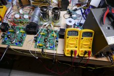
I'm a little behind in my build, but the discussion prompted me to build and test my Mos supply. I am using a Triad N68-X as well. My negative and positive supplies come up right away and are steady at -143 and + 143. I am using the red wires as my primaries and have tied the yellow/black and red/black together to ground. That leaves the black and green/black for the other connections.
This was without any load.
Jacques
This was without any load.
Jacques
Hi George,
As I’m getting ready to connect my power supply to the board and the board to the power tubes I want to make sure that my understanding of the connections is correct.
Do I need to hook anything up to H3 on the UDC board? Is that where the center tap for the 6.3V circuit goes?
DRV2-2 and DRV1-1 will connect to pin 5 of the power tubes.
DRV2-1 and DRV1-2 will connect to pins 8 and 1 of the power tubes.
Pin 3 of the power tubes will connect to the output transformer.
Pins 2 and 7 to the heater circuits.
If I’m running in triode mode I don’t need to hook up the screen?
For testing can I substitute an EL34 for a KT88?
thanks, Jacques
- Home
- More Vendors...
- Tubelab
- Tubelab Universal Driver Board, 2015 version