but I've got a stash of really nice iron in the closet saying "use me"...
Yeah, I have two pair of 400 watt Plitron toroidal OPT's. I have had one pair for like 10 years. They have been used in test amps several times including one of Pete's big red boards stuffed with 35LR6's, both channels wired in parallel, and fed from a 650 volt power supply capable of 1.7 Amps. The result was 525 watts.
So, it would be easy enough to wire up two big red boards, stuff in 8 X 35LR6's and build a kilowatt level 650 volt power supply using 3 X 600 VA 120/ 240 volt isolation transformers. I have had all these parts for years, but haven't wired them together....but the OPT's keep calling me, saying "use me."
I have no need for a kilowatt tube amp, nor any speakers capable of eating that power, but it would be cool. If I were to build something like that, it would be a Tubelab showpiece, and therefore not just two of Pete's boards wired together.
About 10 years ago I designed and built a rather unique SE vacuum tube amplifier using a technique I developed in the cell phone world called supply modulation. Primarily used for efficiency improvement, it allowed a single 6AS7 to produce 30 watts of audio. This used a Microchip dsPIC controller and won a prize in a Microchip design contest resulting in an article published in Circuit Cellar magazine.
I have thought about applying this technique to a powerful push pull tube amp but there are some serious design hurdles that need to be overcome.
Recently I have developed a new topology for vacuum tube circuits that shows promise and has led to a working 50 WPC amp with tiny 9 watt TV sweep tubes and an Antek toroid for power. It makes 80 watts on a good power supply. Scaling this up to 500 watts, should require 90 watts worth of tubes, or two pair of 36LW6's.
Excuse me.....I hear the tubes and transformers calling...use me...use me....maybe next year.
Bob Carver made his career undersizing power transformers
As did Leo Fender....and that gave birth to the rock n roll distortion that we all know and love....it all started with Leo pinching pennies on power transformers driving guitarists to turn things up to 11.
Much of the distortion comes from undersized OPT's. Compare the physical size of the OPT in a Marshall to a Fender of equal power output ratings. The Marshall is at least twice the size. This is the biggest reason for the different sound.
Back in high school there was a saying, "never play bass through a Bandmaster." One of my friends didn't believe it and liked the unique sound the saturated OPT provided, but one day it blew. Fortunately he had the proper fuse, and thus only needed new 6L6GC's and power supply diodes. The output tubes would glow red on bass notes and the screen grids could be seen pulsing to the beat!
Leo never imagined how guitarists would learn to love that distortion and use it effectively in their playing.
I found an interesting combination of bias points.
The 6N1P are biased at Va=70V and the 6CG7 are biased at Va=220V
Distortion up to 20W remains well below 1% and is dominated by 2nd harmonic which is greater than 20dB above third.
If I set Va to 105, overall distortion is lower, but primarily due to 2nd harmonic being lower.
6N23P and 6DJ8 do not perform the same way. That is, dropping Va to 70V does not result in slightly lower odd harmonic and much larger even harmonics, particularly 2nd.
my available Tubelab time needs to go toward the redesign of the TSE. A new thread will be started for that subject, and it will need a lot of attention.
Dear George, any news in this topic? When would you publish it and what changes will be made in the original design? I built four TSE and I am big fan of this amp. Would be delighted with the new version.
Dear George, any news in this topic? When would you publish it and what changes will be made in the original design? I built four TSE and I am big fan of this amp. Would be delighted with the new version.
The new thread is here....
After a 14 year run, the TSE must DIE!
I'm a big fan of this amp too..built 2...300B and 45.....the 300B version is my favorite amp.
Ok..time for some questions....
I'm assuming that mosfet followers/powerdrive significantly reduce the need for current out of the driver stage to charge/discharge the output tube's miller capacitance.......
If this is the case why does the TSE need the gm of the 5842's? ....seems like lots of driver tubes would work...I understand that we need some current capability to charge/discharge the capacitance of the mosfet gate.....seems like we could trade some gm for some voltage swing when using mosfets..maybe trade lots of gm for voltage swing.
I just stumbled across some tubes from my old CJ Premier 11A..6CG7's and 6550's.....so if these are a good combo without mosfet followers what does adding them between stages do for us?
why does the TSE need the gm of the 5842's? ....seems like lots of driver tubes would work..
The predecessor to the TSE came to exist in the late 1990's. I had traded my very first car, now about 40 years old, for a Scott 272 tube stereo amp, which kicked my Carver / Phase Linear stuff right out of the stereo rack.
A friend who is a military surplus dealer calls me and says he has just bought about 20,000 square feet of abandoned military surplus and he has 30 days to remove EVERYTHING. It seems that someone found hazmat during the demo of an old building......you guessed it, tubes full of mercury. He tells me that there are lots of tubes, and I can have them all for free it I help him load it all and move it about 20 miles.....but it's in Orlando about 200 miles from my house. I spent all 4 weekends, and a few weekdays loading stuff, and bringing a trailer full of tubes home every trip......best guess, bsaed on number of boxes, weight and counting a couple of the small boxes, over 100,000 tubes!!!
Maybe 1/3 of these tubes were broken, and more were unusable. Then there was all the unwanted stuff that got sold or given away by the truckload. There were still 25,000 or so useful tubes, all used, unboxed, unsorted and untested. It took me over 5 years to sort them all!
I had been making tube guitar amps for several years after a long period of silicon destruction, maybe its time for a tube stereo. I started making the usual KT88 push pull stuff, but the internet kept telling me that a low powered SE amp was what I needed, and the 300B was the trendy tube of the day. I couldn't understand how anyone would be happy with 2 to 8 watts, so I decided that my first 300B amp would be P-P. It was known as the 300Beast, it ROCKED, and was the only amp from the old days that I kept. It still sits on the shelf awaiting a rebuild as it's power supply lost all the magic smoke probably 10 years ago.....I'm thinking it's an excellent place to put these driver boards.
I had some 45's, 2A3's, 811A's, 809's, 211's, 845's and a bunch of other tubes that the audio nuts of the day deemed "proper." I had made a few SE amps using the trendy schematics of the day SRPP feeding a 45, or two stage 6SN7 feeding a 45 or 300B, I was not impressed. I had built an 845SE amp using a magazine schematic called "the poor man's Ongaku" and was also quite unimpressed. I wanted an amp that could use the 45 for output, or to drive the 211 or 845 so I decided to make my own.
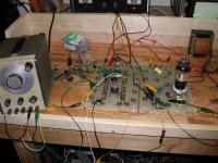
I had made this vacuum tube breadboarding thing that I called the Tubelab for guitar amp design (yes, that's where the name came from). I simply breadboarded up a 45 output stage, and started trying different driver circuits and tubes.....I didn't like any of them.
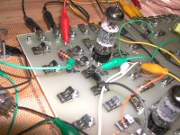
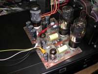
I have some old pictures of these experiments. The first two show a pair of tubes (probably an SRPP circuit) driving a 45, built up on the Tubelab. Note that the 45 is still being fed through a coupling cap, a trendy Wonder Cap at that (the yellow one). Early vintage FFT pictures told me why!
I grew tired of the SRPP and the two stage driver designs. Could a single stage deliver the needed gain and drive voltage? Conventional wisdom of the day said NO. I tried every high Mu triode that I had, and either there wasn't enough gain, the distortion was too high, or the frequency response was rolled off.
How could I get more gain. Remember I wanted to use this as a driver for a BIG triode as well as a stand alone two stage amp, so I got out the big tube and wired it into the Tubelab. My thought was that I could run say 1000 volts of B+ and a very LARGE plate load resistor to get more gain. Yes. I got more gain (and a couple of dead 12AX7's), but capacitance and low Gm was causing high frequency rolloff. As with most of my experiments, I rolled through just about every tube that I had that could possible work.
I remember a special kind of constant current diode that we used in satellite TV receivers in the 80's, and Digikey still had some in stock, so I ordered some. I also found some neat new magic parts in the Digikey catalog while looking for CCS's.
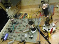
A careful look at fuzzy picture number 3 shows that the top tube in the driver board is gone and there is a mosfet sticking up in front of the brown cap in the top left corner. The constant current diodes are still in their clips (gold leads), but no longer connected up. I had discovered that new piece of magic we now know as the IXYS 10M45 (behind the brown cap) .....PowerDrive, was born......
So there is a second PowerDrive circuit mounted on the black heat sink behind the 211 tube. Yes, there is 900 volts wired up using cheap Radio Shack clip leads.
The 5842 just happened to work the best of everything I tried, and I had a couple hundred of them. They were about $5 at the time (early 2000's) so I left it there.
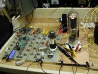
I found a picture of the very first TSE proto board. Note that the board went through some changes early on. I was cooking up DIY PC boards on my kitchen stove one or two at a time and selling complete amps. This board could never use 300B's. The heat sinks were added and the power supply was upgraded to handle the higher voltages for the 300B tubes.
The Gm of the 5842 was not the major factor in choosing it. The TSE was originally conceived with 45's as the output tube of choice. The main factors for the input tube was the need for gain, far more that the typical 6SN7 could provide. It would also need to provide a hundred volts P-P of drive or more as well. I had over a dozen tubes with high Mu that would work, the 5842 just happened to work the best. Now that they are not so common, or cheap there might be something better. A contender at the time was the 6J4, but 7 pin sockets were not common yet.
The UD board does not have the gain requirements that the TSE had since there are two stages. This leaves plenty of tube choice options. I have had prototypes of these driver boards in use since 2009 with both octal and 9 pin tubes. The 6SN7 (and 6FQ7 / 6CG7) are regarded as some of the most linear triodes ever built, and I have found no reason to dispute that, so they have been my tubes of choice for most designs. If more gain is needed, the first 6SN7 can be replaced with a 6SL7, with resistor value changes. For the 9 pin tubes, there are a variety of possible combinations. I have used the 6DJ8/6922 for higher gain. The 6BQ7, 6BZ7 or 6BK7 work well too.
if these are a good combo without mosfet followers what does adding them between stages do for us?
The real reason for the mosfet followers were to remove blocking distortion caused by the coupling cap, and allow class A2 or AB2 operation that was prevented by the coupling cap.
Attachments
Last edited:
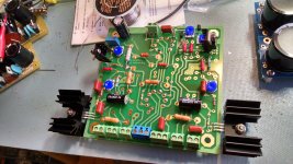
So I've got the various boards built and tested....
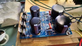
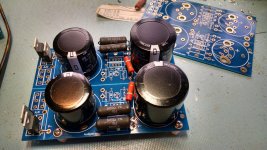
For the B+ and MOSFET +/- supplies I used some Peter Daniels (audiosector) power supply PCBs I had stashed. The boards and mirror imaged and set up for bridge rectification for SS amp supplies. These works great for the MOSFET supplies.
For the B+ supplies they are both wired for B+ and full wave rectification...and the creepage clearances look reasonable. The present plan is to make mono blocks and snap these apart..one in each amp.
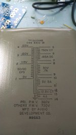
I have a pair of the power transformers shown below and a pair of Triode PA060 transformers. I also have a pair of 4A Hammond 6.3V CT filament transformers. I would prefer to use these power transformers but unfortunately these power transformers only have a 12VCT filament supply....can I successfully use this to power the 6CG7 filaments? ......say by grounding (or biasing up to 75 volts or so with a B+ voltage divider) the CT and connecting the ends of the winding to H1 and H2 and not connecting anything to H3?..not quite clear on the filament windings.....
I'm also assuming that I need to ground MOS-2, DRV1-2, DRV2-1 and B++-1 to a signal ground along with the ground side of the inputs.
For the B+ and MOSFET +/- supplies I used some Peter Daniels (audiosector) power supply PCBs I had stashed. The boards and mirror imaged and set up for bridge rectification for SS amp supplies. These works great for the MOSFET supplies.
For the B+ supplies they are both wired for B+ and full wave rectification...and the creepage clearances look reasonable. The present plan is to make mono blocks and snap these apart..one in each amp.
I have a pair of the power transformers shown below and a pair of Triode PA060 transformers. I also have a pair of 4A Hammond 6.3V CT filament transformers. I would prefer to use these power transformers but unfortunately these power transformers only have a 12VCT filament supply....can I successfully use this to power the 6CG7 filaments? ......say by grounding (or biasing up to 75 volts or so with a B+ voltage divider) the CT and connecting the ends of the winding to H1 and H2 and not connecting anything to H3?..not quite clear on the filament windings.....
I'm also assuming that I need to ground MOS-2, DRV1-2, DRV2-1 and B++-1 to a signal ground along with the ground side of the inputs.
Attachments
Last edited:
connecting the ends of the winding to H1 and H2
If you mean pins 12 and 14 when you say "ends." NO, don't do that you will feed 12.8 volts to the 6CG7's making them very unhappy.
The transformers you have are fine for powering up one mono block each. I can think of a few ways to do this, but let's go for the easiest. We are going to power up driver heaters with one half of the winding, and the output tube's heaters with the other half.
Each half supplies 6.4 volts at 4 amps. The driver board needs 1.2 amps (2 X 600 mA) and the output tubes need 3.2 amps (2 X 1.6 A), so there is enough power for all the heaters. Look at this as two separate 6.4 volt 4 amp windings. They just happen to be connected together which is not a problem here.
Connect one end of the winding, pin 12 to H1.
Then connect the CT, pin 13 to H2. That will supply 6.4 volts to the board to light the 6CG7's. Now connect the CT (pin 13) also to either pin 2 or 7 on BOTH output tubes. Also connect the CT to the resistive divider that elevates the heaters to about 70 volts. It is usually good to put a capacitor across the resistor in the divider that goes to ground. It helps cut hum. I use .33 uF 250 volts because I have a big bag full of them but anything over .1 uF and 100 volts is good.
Connect the other end, pin 14 to the other heater pin (2 or 7) on BOTH output tubes.
It is usually best to run a separate pair of lightly twisted wires from the transformer to the driver board, and to each output tube. You can chain the output tubes if your wire is good for 4 amps.
I need to ground MOS-2, DRV1-2, DRV2-1 and B++-1 to a signal ground along with the ground side of the inputs.
All of them are connected together on the PC board. Electrically only one of them needs to be connected, but I find that this method eliminated ground loops and hum:
Run a piece of shielded cable, or a twisted pair of wires from the input connector on the board to the input connector of the amp. Make sure that the ground side of the input connector (IN 2) goes to the ground side of the input connector.
Run a wire from MOS 2 to your +/- 160 volt board's ground connection. This
Run a wire from B++ 1 to your B+ board's ground (negative) connection.
You will need a method to measure the current in each output tube for setting the bias. I put a 1 ohm 2 or 3 watt 1% resostor in series with each cathode. Measure the DC VOLTAGE across this resistor, them 1 mV is equal to 1mA. Set the tubes to the desired idle current by adjusting the corresponding bias pot on the board. Somewhere between 40 and 80 mA (mV).
Connect one end of the 1 ohm resistor to pin 8 of the KT88. Run a wire from DRV1-2 to the other end of this 1 ohm resistor.
Repeat with DRV 2-1 and the other KT88.
Thanks George! Completely clear on the heaters...technically I'm slightly shy on heater current with those transformers but I'll see how it goes.
I randomly pulled out a few 6CG7's and measured the resistance from pin 4 to pin 5 and then either of those pins to pin 9....it looks like pin 4 to pin 5 is around 2 ohms and every one of the 6CG7's had no connection from those pins to pin 9. I also discovered that a couple of the leftover tubes from the CJ premier 11a are 5751s, and these are around 14 ohms pin 4 to pin 5 and around 7 ohms from either of those pins to pin 9....which makes sense since they are 12V filaments.
I'm also completely clear on the 1 ohm cathode R for the output tubes..or thereabouts...
Next question......I'm assuming that I'm tying the screen to the plate with a 2W 100R resistor for KT88 triode connection? Or tie both the screen and suppressor grids together then 100R to plate? I've seen it done a few different ways for triode wiring...
Last edited:
6CG7's had no connection from those pins to pin 9
The 6CG7 should have no connection at all to pin 9 and the 6FQ7 should have an internal shield between the two sections connected to pin 9. I have however found several exceptions to this rule, and plenty of tubes wearing both numbers with or without the shield.
Pin 9 is the heater center tap on 12 volt tubes like the 12AX7, 12AU7, and as you found, the 5751.
The 5751 does work well for the input tube in this board, but it must be paired with another 12 volt tube like the 12AU7, 12BH7 or 5963, and a different heater wiring scheme would be required.
I'm tying the screen to the plate with a 2W 100R resistor for KT88 triode connection?
Yes.
Or tie both the screen and suppressor grids together then 100R to plate?
The suppressor (beam plates) is tied to the cathode internally in the KT88, 6550, and 6L6GC.
You can connect pin 1 directly to pin 8 if you ever want to run EL34's in this amp. The metal ring around the base in some KT88's and 6550's is connected to pin 1, so this ring should not be externally grounded (say with a base tube clamp) if you want to do this.
I for one sure don't see a problem raising the price of boards. When you look at what they get for tubes and boutique caps these days, the boards are a walk in the park. I've built all 3 of your boards and love them, but if I didn't have a few 45s in the first place, I would have skipped that build. I'd like to see something that sounds good and uses cheap, unpopular tubes. What that might be, I have no idea.
Can the LTP/driver boards be used without the source followers and without a separate +/- 150v power supply?
I ask because I am designing around a 400v B+ and 7k6 output transformers (from an EL84 amp) so a pair of KT88 UL will be biased heavily into class A and far from grid conduction, so the source followers won’t be required for their purpose. It would be handy to leave it out since I’m building monoblocks. My Tubelab SPP has been working lovely since I built it back in 2014, but it is time for an upgrade, and I’d like to reuse the transformers.
Also, is it possible to use a CCS in the tail of V2 instead of at the plates, to ensure perfect balance? Or have I misunderstood how it works.
Great to see you working on new designs and reading about the development here George.
Can the LTP/driver boards be used without the source follower
Yes, simply omit the mosfet, it's source resistors, and place a jumper in the PC board between the gate and source pins where the mosfet should go.
I have done this when one driver board is used to drive multiple pairs of output tubes, and a separate bias adjustment is desired for each tube. In this case I also bypass the coupling cap, and omit all of the bias parts. There are mosfets, coupling caps and bias parts on each individual output board.
Even if the output tubes are in deep class A it may be possible to drive them toward or into the positive grid area. This will alter the charge on the coupling cap causing a bias shift and an associated recovery time. This can cause "blocking distortion" and is why I created the PowerDrive (mosfet) concept in the first place. If the amp has sufficient power reserves such that it will rarely if ever see clipping, you could leave the mosfets out, if not consider keeping them. Distortion caused by clipping or blocking is far worse than whatever real or perceived distortion is created by entering A2.
and without a separate +/- 150v power supply?
The positive supply is not needed if the mosfets are removed. A negative supply is still needed for the CCS in the tail of the first pair (V1). It needs to supply the full tail current which is from 2 to 15 mA depending on the tube being used. It should be -20 volts or more. It can be derived from the heater supply, or from the output tube bias supply if it is capable of the current needs of V1.
Also, is it possible to use a CCS in the tail of V2 instead of at the plates
It IS in the tail of V2. See the schematic in post #2 of this thread. Early versions of the driver board (2005 - 2007) had a CCS in each plate of V2 for gain / drive voltage reasons. It was unstable and was eliminated. Since the cathodes of V2 operate in the 90 to 125 volt range, no negative supply is needed for this tail, it's tied to ground.
Many thanks George, and apologies, I was working from a different schematic you posted.
Since you haven't suggested it, I don't suppose it's possible to derive the +150v from the B+, and the -150v from a negative full-wave rectifier from the main power transformer, a bit like a bias supply when you don't have a bias tap? The mosfets require 10-20mA and the CCS 10mA so that would be 25mA for each rail? If it's not possible to do this I will use the 50V bias tap for the bias supply and CCS.
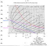
How does my load line look? I've got two different sets of KT88 ultralinear curves so I've plotted both. I'm working with Hammond 370HX 550V@ 230mA and 1650FA 25W 7,600k
Since you haven't suggested it, I don't suppose it's possible to derive the +150v from the B+, and the -150v from a negative full-wave rectifier from the main power transformer, a bit like a bias supply when you don't have a bias tap? The mosfets require 10-20mA and the CCS 10mA so that would be 25mA for each rail? If it's not possible to do this I will use the 50V bias tap for the bias supply and CCS.
How does my load line look? I've got two different sets of KT88 ultralinear curves so I've plotted both. I'm working with Hammond 370HX 550V@ 230mA and 1650FA 25W 7,600k
Attachments
- Home
- More Vendors...
- Tubelab
- Tubelab Universal Driver Board, 2015 version