do you still have boards left?
At this moment there are 6 boards left. I will get some more when funds permit (soon).
Hope everything is going okay with you.
I'm fine. Tubelab has barely paid its bills for the last couple of years, so I took on the paid contract job mentioned above to pay the bills and fund some new stuff that could happen next year. This means that tubes will stay cold for a while, and I may not be here as often as usual. There are two or three amps that are partially completed using these boards, and something new that will develop into some new SE and P-P amp designs.......
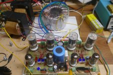
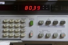
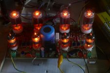
Meanwhile this prototype sits dark on the bench. It makes 50 WPC on that Antek Toroid, and 80 WPC on a regulated power supply. It will likely be a new Tubalab board next year. There is an SE flavor that is in the early perf board proto stage. So far it only exists in simulation.
Attachments
I'm speaking as a longtime lurker here, but it's good to hear you're okay. Not as many sparks - or as much smoke - rolling out of your shop as in your Florida days, regrettably, but it's gratifying to hear of more good things to come. Hey, we can't be exploding things all the time now right? I'll definitely stay tuned regardless...
Paperweight: I used to live in Asheboro until about six years ago. Before the move I was working on a pair of KT88 monoblocks based on an old Acrosound circuit (itself another incarnation of the Williamson amp), but then my work made me an offer I couldn't refuse. In a way I'm glad it did, as this driver board appears to be a much better front end for this circuit. But it'd have been great to have someone to have a fellow conspirator just a few miles down the road.
And so as not to stray too far off-topic, I'm off to the basement to look for those parts...
Last edited:
I don't get out of the house very often except to go to work. My brother stopped by today and we swung by a model train hobby shop in Spencer. Then we went to Sauers Veneers. If you're into building speakers, guitars, furniture, etc those guys have some amazing stuff. I want to eventually build a set of Jim Holtz and Curt Campbell's Bordeaux speakers. I'm waiting for the cabinet kit to show up on Speaker Hardware.
I ended up buying a set of 60 watt output transformers from Dynakitparts.com and a pair of Classic Tone 40-18069 power transformers. The power transformers can be wired for a good number of B+ configurations and has plenty of current available.
I ended up buying a set of 60 watt output transformers from Dynakitparts.com and a pair of Classic Tone 40-18069 power transformers. The power transformers can be wired for a good number of B+ configurations and has plenty of current available.
I finally got a chance to play with the driver board again as I'm home taking care of my ex while she goes through Chemo.
I have a 6N23P in the first position and a 6CG7 in the driver position.
I'm not running any feedback
Output is a pair of 6S3P with an Edcor CXPP30-MS-5K opt with a B+ of 350V.
The 6P3S are biased around 25mA for class AB1 because I can't get more out of one position. I think I need to diagnose the bias supply in that channel before I go on.
Best I can do so far is 10Vrms out before clipping with the lowest bias set of tubes I have.
I swapped to a hotter set of tubes (32mA at -37V bias) and got 21W out which is probably getting close to expected.
I can't get Audio Tester to run any more, so I've switched to ARTA.
Changed R26 and R36 from 150K to 60K and got the bias range I think will work for most of the tubes I want to experiment with.
Bias is set at 44mA with 360V B+.
One of my 6N23P has a bad section which was causing distortion problems.
I now get glitches at about a 6.28ms interval that I have to trace down. It is not line rectification related, so I guess it's shotgun time.
Bias is set at 44mA with 360V B+.
One of my 6N23P has a bad section which was causing distortion problems.
I now get glitches at about a 6.28ms interval that I have to trace down. It is not line rectification related, so I guess it's shotgun time.
I reworked my system ground and think the noise was coming in on mains.
I'm having a bit of trouble getting the bias set on the input stage.
I'm using a 6N1P biased around 115Vak, and Ia about 4.5mA.
I see a considerable difference between the gain of the two stages.
As I adjust R10 to shift the bias balance between the two tube sections, I see the total bias shift in addition to the bias split between the two tubes.
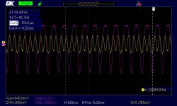
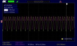
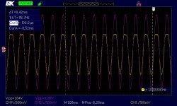
Also I see a shift in the AC voltage on the anodes starting with the higher output shifting down and clipping (plate voltage does not go near saturation), and eventually almost looking like a frequency doubler.
Continuing adjusting the balance R10, results in the reverse sequence with the channels swapping amplitudes.
I'm having a bit of trouble getting the bias set on the input stage.
I'm using a 6N1P biased around 115Vak, and Ia about 4.5mA.
I see a considerable difference between the gain of the two stages.
As I adjust R10 to shift the bias balance between the two tube sections, I see the total bias shift in addition to the bias split between the two tubes.
Also I see a shift in the AC voltage on the anodes starting with the higher output shifting down and clipping (plate voltage does not go near saturation), and eventually almost looking like a frequency doubler.
Continuing adjusting the balance R10, results in the reverse sequence with the channels swapping amplitudes.
Attachments

Last edited:
Well, I don't know why, but attaching the probes and meter clips to the anode resistors of V1A and V1B seem to cause this issue.
If I hook the probes to the anodes of V2A and V2B, I can adjust the setup without the funky frequency doubling.
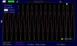
I am now getting about 1W out of the 6P3S with 0.66%thd. Nice waterfall drop off with frequency.
I still am not running any feedback.
If I hook the probes to the anodes of V2A and V2B, I can adjust the setup without the funky frequency doubling.
I am now getting about 1W out of the 6P3S with 0.66%thd. Nice waterfall drop off with frequency.
I still am not running any feedback.
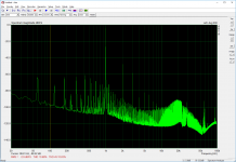
Typical distortion with a 6DJ8 driving a 6CG7.
I get pretty much the same distortion profile with either 6DJ8, 6N1P or 6N23P as the input tube.
The only adjustment I need to make is the balance to get the output tubes close. If they are out by more than +/-2V (typical 220V at anode) distortion goes up rapidly.
The garbage at the bottom is power line related, this is spread out on a bench with a lot of leads to pick up radiated noise.
I guess my next work will be with feedback.
First will be GNFB, then Plate to grid.
Attachments
Last edited:
GFB recommendations
Please see my post no. 272.
Is there a recommended configuration for GNFB from the output of the OPT to the grid of V1B?
Please see my post no. 272.
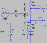
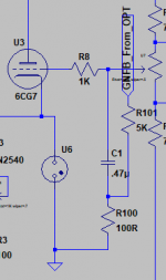
For global negative feedback George recommended adding a 100Ω resistor between the 0.47uF capacitor and ground and running the negative feedback via a 5k resistor to the junction of the capacitor and resistor.
In my simulations I've run a 2.5K feedback resistor without a problem. Gave me about 10dB of feedback I think.
This isn't clear. Does the new 100R resistor go in parallel with C1, and the feedback go through the 5 resistor to the junction of C1, R8, the new 100R resistor and the pot output?
Attachments
Last edited:
No, lift the ground end of C1 out of the board and wire a 100 ohm resistor in series with the cap. The resistor goes between the ground hole in the board and the lead on the capacitor that you just pulled out of that hole. Then inject the feedback into the junction of the cap and resistor. This is done with as resistor in the 4000 to 10,000 ohm range from the speaker terminal. Most OPT's will also work better with a small cap across this resistor.
If a phasing issue causes the amp to oscillate, swap the plate leads on the OPT.
If a phasing issue causes the amp to oscillate, swap the plate leads on the OPT.
I think I'm running into AB2 territory as Vgk is +10V peak.
I'm getting 26W out with a 5K opt, 400V B+ with a pair of Russian/Soviet erra 6P3S.
2nd harmonic exceeds 3rd, but 5th is above both.
THD is 2.6% going into clipping on the positive peak at the OPT (8R load). I suspect one tube has much higher Gm than the other as clipping is asymmetrical.
I'm getting 26W out with a 5K opt, 400V B+ with a pair of Russian/Soviet erra 6P3S.
2nd harmonic exceeds 3rd, but 5th is above both.
THD is 2.6% going into clipping on the positive peak at the OPT (8R load). I suspect one tube has much higher Gm than the other as clipping is asymmetrical.
Oops, blew up my sound card. I was getting 40+ W out at 450V B+ and had the resistor divider string to the sound card in the wrong position.
Looks like I'll buy another cheap sound card off amazon.
I think I will rework my wiring to the computer and bury a resistor and zener clamp circuit in series with the audio input to form a protection network for the future.
Looks like I'll buy another cheap sound card off amazon.
I think I will rework my wiring to the computer and bury a resistor and zener clamp circuit in series with the audio input to form a protection network for the future.
All of the current batch of these boards are gone.
Another batch will be ordered as soon as funds are available. The issue with my cloned debit card and emptied bank account has been fixed, but I'm still waiting on a large check.
There are two possible paths here:
1) Order another batch of boards that are identical to these. This is the quickest and cheapest option, and involves zero risk.
2) Make any desired changes and resubmit the board. This requires layout changes and generating new artwork files. Any board changes involve risk, and additional tooling charges. To mitigate the risk, I always spin a DIY test board, populate it and test it. This adds considerable time to the job, which is in short supply right now. It also adds a $100 tooling charge, which gets adds another $4 to the board cost for a 25 board purchase.
As of now the only change I would make is to add a second input connector so the GNFB or differential inputs could be used without lifting a capacitor lead.
My current choice is to leave the board alone and order more as soon as funds arrive. Any thoughts?
I'm currently busy with a contract job, and my available Tubelab time needs to go toward the redesign of the TSE. A new thread will be started for that subject, and it will need a lot of attention.
All of the current batch of these boards are gone.
Another batch will be ordered as soon as funds are available. The issue with my cloned debit card and emptied bank account has been fixed, but I'm still waiting on a large check.
There are two possible paths here:
1) Order another batch of boards that are identical to these. This is the quickest and cheapest option, and involves zero risk.
2) Make any desired changes and resubmit the board. This requires layout changes and generating new artwork files. Any board changes involve risk, and additional tooling charges.
FWIW, my vote is #1. I've spent a fair amount of time, energy, and $ to produce what I, and others, believe is a commendable set of amps. As more builders take on the existing UDB, more knowledge will be forthcoming. Like the old dog said "lifting a leg is all in a day's work."
Seasons greetings to all.'
Warren
There are two possible paths here:
1) Order another batch of boards that are identical to these. This is the quickest and cheapest option, and involves zero risk.
2) Make any desired changes and resubmit the board.
If you go for option 2 provision for elevating the heater of V2 would be good.
Unfortunately that would require an additional terminal block for which there isn't any room.
provision for elevating the heater of V2 would be good.
As you noted getting another terminal block in there would mean taking one out, or making the board bigger. Either would mean a total re-layout. I usually elevate the heaters for both tubes to 50 - 70 volts for most cases. That puts the heater 50 to 70 volts more positive that the cathode of V1, which is within spec, and well below 200 volts more negative than the cathode of V2 (in spec) even with signal swing. This assumes a 6CG7 or 6FQ7 for V2. It's worth a check and possible voltage change if other tubes are used.
- Home
- More Vendors...
- Tubelab
- Tubelab Universal Driver Board, 2015 version