I recently purchased this amp from an estate where the deceased person had built this amp. I received the amp with no tubes or information about the build. I'm hoping someone can help direct me as to what tubes are needed and any other information that can help me get it up and running. It looks like it was done with skill and quality parts, I would love to honor the builder by enjoying his creation. I have read some information on the tubelabs website, but it seems this amp could be built to use different tubes and have different specs, any help will be greatly appreciated.
Attachments
GSX Steve,
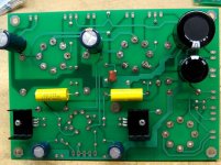
This looks like George Anderson's Tubelab Simple SE - a very good sounding single ended tube amplifier!")
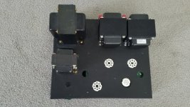
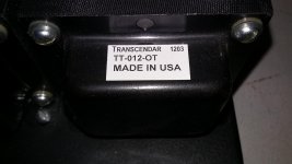
What does the sticker on top of the output transformer say? Are these transformers covered in a cloth-like material?
For the signal tube (small 9 pin socket in the front) you will need a 12AT7 (AKA ECC81). The 8 pin lone socket in the front is for the rectifier tube - a good 5AR4 should work (I've used Sovtek). The pair of 8 pin sockets at the back are for the output tubes - EL34, 6L6, 6CA7 - all of these should work if this is a stock build.
What is your level of expertise when it comes to electronics? Please note that tube amplifiers carry lethal voltages inside - so you need to be very careful when working with them.
This looks like George Anderson's Tubelab Simple SE - a very good sounding single ended tube amplifier!
What does the sticker on top of the output transformer say? Are these transformers covered in a cloth-like material?
For the signal tube (small 9 pin socket in the front) you will need a 12AT7 (AKA ECC81). The 8 pin lone socket in the front is for the rectifier tube - a good 5AR4 should work (I've used Sovtek). The pair of 8 pin sockets at the back are for the output tubes - EL34, 6L6, 6CA7 - all of these should work if this is a stock build.
What is your level of expertise when it comes to electronics? Please note that tube amplifiers carry lethal voltages inside - so you need to be very careful when working with them.
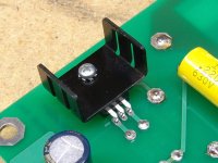
I'm not entirely familiar with this amp, but it doesn't look like the heat sinks on the mosfets are installed correctly - this could lead to overheating in those parts.
Very good observation!
Attaching two images from Tubelab's website for your reference:
Semiconductors | Tubelab
Attachments
Last edited:
GSX Steve,
This looks like George Anderson's Tubelab Simple SE - a very good sounding single ended tube amplifier!
What does the sticker on top of the output transformer say? Are these transformers covered in a cloth-like material?
For the signal tube (small 9 pin socket in the front) you will need a 12AT7 (AKA ECC81). The 8 pin lone socket in the front is for the rectifier tube - a good 5AR4 should work (I've used Sovtek). The pair of 8 pin sockets at the back are for the output tubes - EL34, 6L6, 6CA7 - all of these should work if this is a stock build.
What is your level of expertise when it comes to electronics? Please note that tube amplifiers carry lethal voltages inside - so you need to be very careful when working with them.
I don't have the amp in my possession yet, and my zoom feature does not show the numbers clearly enough so I will have to wait until it gets here. I know a little about tube equipment, I have recapped some Fisher tube amps but just replaced components. I do know about the dangers and have measured voltages before without problems.
Very good observation!
Attaching two images from Tubelab's website for your reference:
Semiconductors | Tubelab
Oops, yup that's what I thought; Steve you will need to address that issue.
Oops, yup that's what I thought; Steve you will need to address that issue.
Okay thanks, hopefully I can get a picture showing how they should go.
I am pretty sure the OPT reads 7T412-OT if that helps with anything.
Very good observation!
Attaching two images from Tubelab's website for your reference:
Semiconductors | Tubelab
Great, that is very helpful, thanks!
Very good observation!
Attaching two images from Tubelab's website for your reference:
Semiconductors | Tubelab
I suppose I will need someone familiar with this board to determine if it is a stock build or not since that could determine which tubes it was built for.
It is indeed a Tubelab SSE, looks to be the first variation of the board.
By all means, if you are unfamiliar with high voltage electronics, heed Zman01's admonition about becoming informed as to how to work around stuff that can kill you.
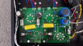
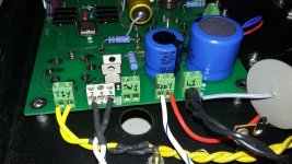
it has the solid state rectifiers installed. These have been problematic for some people, including myself. I can't tell if they are jumpered in or out from the picture.
The heatsinks are backwards. The 10M45 CCS does get hot enough to require a heatsink with the specified 330 ohm current set. These chips may or may not be good at this point. The heatsink will have B+ on it, so be careful. See above admonition.
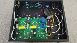
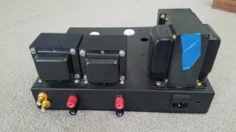
OPT's look like Transcendar 10 watters - a good choice and unobtainum at present. The label should give the load - I believe TT-010 is 3K, and TT-012 is 5K, but I am at the office and my OPT's are back at home. The Transcendar website was up last I checked, and the information is there.
Can't tell anything about the power transformer and choke, other than that the choke looks good sized.
It's jumpered for triode operation, cathode feedback is not enabled.
The front end tube should be 12AT7. Rectifer is 5AR4, typically. For power tubes, I would start with some cheap 6L6GC and a cheap 12AT7 to get it up and running. I would not use a cheapo 5AR4 - that is asking for grief in my experience. The Sovtek 5AR4 is okay.
Where is the fuse? In the power socket? Check it - if it is blown, could be a bad sign. The first thing I would suspect would be those rectifier diodes. If it is not blown, put some tubes in it and power it up using some 8 ohm resistors for dummy loads on the speaker terminals, and start checking voltages.
These are simple amplifiers and it should not be hard to get it up and running; the success rate here is 100% AFAIK. Probably will work fine right off the bat.
Win W5JAG
By all means, if you are unfamiliar with high voltage electronics, heed Zman01's admonition about becoming informed as to how to work around stuff that can kill you.
it has the solid state rectifiers installed. These have been problematic for some people, including myself. I can't tell if they are jumpered in or out from the picture.
The heatsinks are backwards. The 10M45 CCS does get hot enough to require a heatsink with the specified 330 ohm current set. These chips may or may not be good at this point. The heatsink will have B+ on it, so be careful. See above admonition.
OPT's look like Transcendar 10 watters - a good choice and unobtainum at present. The label should give the load - I believe TT-010 is 3K, and TT-012 is 5K, but I am at the office and my OPT's are back at home. The Transcendar website was up last I checked, and the information is there.
Can't tell anything about the power transformer and choke, other than that the choke looks good sized.
It's jumpered for triode operation, cathode feedback is not enabled.
The front end tube should be 12AT7. Rectifer is 5AR4, typically. For power tubes, I would start with some cheap 6L6GC and a cheap 12AT7 to get it up and running. I would not use a cheapo 5AR4 - that is asking for grief in my experience. The Sovtek 5AR4 is okay.
Where is the fuse? In the power socket? Check it - if it is blown, could be a bad sign. The first thing I would suspect would be those rectifier diodes. If it is not blown, put some tubes in it and power it up using some 8 ohm resistors for dummy loads on the speaker terminals, and start checking voltages.
These are simple amplifiers and it should not be hard to get it up and running; the success rate here is 100% AFAIK. Probably will work fine right off the bat.
Win W5JAG
Last edited:
It IS an SSE. I don't see any obvious mistakes other than the heatsinks previously mentioned. The chips that they are mounted to don't generate too much heat, so they may live, but a better picture (close up) once you have the amp will help us figure it out.
The amp is wired for triode mode with no feedback, so the most popular output tube for that configuration would be the EL34. The input tube is a 12AT7 or ECC81 or 6201 (these are different names for the same tube). The rectifier tube should be a 5AR4 or GZ34 (same thing).
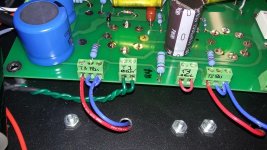
The output transformers look like Transcendars (good choice, but no longer available). I don't recognize the other transformers. The power transformer has brass hardware which isn't common, but could have been builder installed to quiet a noisy transformer.
The amp is wired for triode mode with no feedback, so the most popular output tube for that configuration would be the EL34. The input tube is a 12AT7 or ECC81 or 6201 (these are different names for the same tube). The rectifier tube should be a 5AR4 or GZ34 (same thing).
The output transformers look like Transcendars (good choice, but no longer available). I don't recognize the other transformers. The power transformer has brass hardware which isn't common, but could have been builder installed to quiet a noisy transformer.
Let me more folks have a closer looks at the PCB. Higher res pictures once you have the amp in hand will also help. I guess measuring the voltage at a few points would help determine what tubes can go in.
Thanks everyone for all the information, I will report back once I have the amp in hand. I'm sure with all the helpful members here I will have it up and working well soon. I will see what tubes I have on hand and make sure I have what I need to start testing upon its arrival. Much appreciated everyone!
The amp arrived today, took some close up pictures to maybe help confirm how it was built. Looks like a little straightening out is needed, and getting the tubes needed here.
Attachments
Those coupling caps look like they're .1 uF. They should be .22uF
I will check that, I have some .22's here if need be. I just want to make sure he didn't build this custom for different tubes or something. I appreciate the keen eyes checking everything.
The heat sinks on the CCS chips are OK. The holes for the transformer wires do need some sleeving or a grommet. The sharp metal edges will eventually wear through the wire insulation and bad stuff will happen. .1 uF caps are probably good for most builds. A bigger cap can help the bass when big OPT's are used, but it can actually make things worse with a small OPT and a warped record, or other strong low frequency energy.
- Status
- This old topic is closed. If you want to reopen this topic, contact a moderator using the "Report Post" button.
- Home
- More Vendors...
- Tubelab
- Need tubelabs help