I've only now got around to trying this but I'm not getting the expected screen
voltage, far from it actually.
Last January in this thread I aked a question about lowering the screen
voltage in my low voltage SSE. George suggested using Pete Millet's screen
voltage regulator from his Engineer's Amplifier.
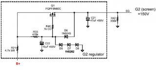
It's a simple circuit based on a mosfet, some resistors and zener diodes.
I used the same mosfet as specified in Pete's circuit FQPF8N60C.
I got all the parts from Mouser.
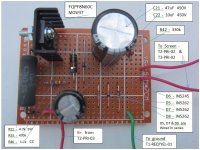
Assembled it on a piece of perf board and wired it to the SSE as per George's
suggestion.
Powered up with a 6087 rectifier,12AT7, 6Y6G power tubes and 680 ohm cathode resistor.
Checking the screen voltage all I'm getting is 78mV, yes that's millivolts,
B+ and Vp are 296V, just about where they should be, normally Vp is several volts
below B+
I am able to play music but with quite obvious distortion.
I measured the voltage going to the input resistor in the circuit (R21 4.7k) and
it is 296V but at the other end it is only 620 millivolts, I'm assuming this is due
to the effect of the rest of the circuit but I wonder if the problem is actually the
resistor.
This resistor gets scorching hot after a few minutes, I can still feel the heat from
it with my hand more than six inches away !!
At the output end of the circuit (R42 330k) going to screen, voltage is just
78 millivolts.
So I'm thinking maybe the mosfet is bad or damaged, I was careful not to overheat
when soldering. I also reflowed all the solder joints to ensure I did'nt have a cold
joint.
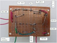
I believe I have the circuit wired correctly. I've attached some photos of the assembly
and a copy of the schematic, maybe George or others can offer comments and suggestions.
voltage, far from it actually.
Last January in this thread I aked a question about lowering the screen
voltage in my low voltage SSE. George suggested using Pete Millet's screen
voltage regulator from his Engineer's Amplifier.
It's a simple circuit based on a mosfet, some resistors and zener diodes.
I used the same mosfet as specified in Pete's circuit FQPF8N60C.
I got all the parts from Mouser.
Assembled it on a piece of perf board and wired it to the SSE as per George's
suggestion.
Powered up with a 6087 rectifier,12AT7, 6Y6G power tubes and 680 ohm cathode resistor.
Checking the screen voltage all I'm getting is 78mV, yes that's millivolts,
B+ and Vp are 296V, just about where they should be, normally Vp is several volts
below B+
I am able to play music but with quite obvious distortion.
I measured the voltage going to the input resistor in the circuit (R21 4.7k) and
it is 296V but at the other end it is only 620 millivolts, I'm assuming this is due
to the effect of the rest of the circuit but I wonder if the problem is actually the
resistor.
This resistor gets scorching hot after a few minutes, I can still feel the heat from
it with my hand more than six inches away !!
At the output end of the circuit (R42 330k) going to screen, voltage is just
78 millivolts.
So I'm thinking maybe the mosfet is bad or damaged, I was careful not to overheat
when soldering. I also reflowed all the solder joints to ensure I did'nt have a cold
joint.
I believe I have the circuit wired correctly. I've attached some photos of the assembly
and a copy of the schematic, maybe George or others can offer comments and suggestions.
Attachments
Sounds to me like you have a direct short between R21 (colder end) and ground. If the FET was short I would expect a little higher than 150V.
The nearest ground for R21 is the ground point for C22. While I can't test continuity between those two points
I'm getting resistance of about 69.6k ohm and I am getting continuity from R33 to ground of C22.
The Drain of your FET must be touching a ground somewhere. What have you got between Drain and -ve C22/21 resistance wise? It should be pretty much Open Circuit.
Yes, you're correct, there is a short between drain and ground but no wires are in contact. However, here's what I've found, R42 has no resistance, I'm measuring only 1.6 ohm whereas it should be 330k, also, I'm getting continuity across that resistor. I always check resistors with my multimeter before installing them and it was okay then. Don't know what happened there.
I find with that sort of perf board that shorts are almost inevitable. I recommend carefully removing a few of the unused pads around various HV circuit points using an x-acto knife. With care you can make this work.
I purchase perf board from vector that does not have any copper on it for these sorts of uses.
I purchase perf board from vector that does not have any copper on it for these sorts of uses.
I also find that type board problematic to work with. I use it for stuff that requires high mechanical rigidity - like RF oscillators - and that's it. Rework - which I always have to do a lot of - is maddening. Regular perf is much easier to build with.
If it makes you feel any better, I just got through letting the smoke out of a transformer that I built around, physically and electrically. Part hasn't been in production for decades, so I'm .....
Win W5JAG
If it makes you feel any better, I just got through letting the smoke out of a transformer that I built around, physically and electrically. Part hasn't been in production for decades, so I'm .....
Win W5JAG
Disappointed to report that the resistor R42/330k is not the cause of the short. When I checked it in circuit I was only getting about 1.6 ohm but
when removed it tested at 327k so it's okay.
It looks like the culprits are those zeners. I isolated them from the rest of the circuit and got continuity between D5 and D8. Also did a diode test on each
of them with my multimeter diode checker and got 0v in both directions. Not sure how or why this happened.
I checked for solder bridges and found none I also checked for shorts between the solder pads close to the HV rail and those close to ground, none found.
Didn't expect to have these problems with such a simple circuit.
I think later I'll assemble a new board, I have spares and I can salvage the caps and resistors from this board.
I'll get perf board without solder pads. How do you guys install mosfets on perf board without solder pads ?
Sounds like the right way to go. Securely attach the heat sink to the board, and use that to secure the mosfet. Once the mosfet is bolted to the sink the leads will not move around.
Make sure you place the gate stopper resistor very close to the gate to prevent parasitic oscillations. (Often in the VHF region where you won't see them easily)
Years ago I designed a small regulator similar to this with an IRF821 or similar and it oscillated, the mosfet fried, gate shorted to the channel and the zeners died. (shorted) A very small resistor or bead on the source may improve stability a bit.
Securely attach the heat sink to the board, and use that to secure the mosfet.
A very small resistor or bead on the source may improve stability a bit.
After the heat sink is attached to the board how do you get the bolt hole on the mosfet to align with the one on the sink ?
In Pete Millet's circuit there's already a 4.7k 5W resistor connected to the source, do you mean another small resistor in addition to this ?
I just push the part through the perf and spread the leads a bit to hold it in place while I wire.
I think Kevin is talking about placing a small resistor, 100 ohms or so, as close to the FET as possible. When you are trying to break oscillation, you want the suppression parts as close as possible to the oscillating device.
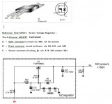
Looking at the schematic, the datasheet for that part, and your pictures, I think you have the connections to the drain and source reversed on that FET. Double check me by all means, but it looks that way to me. There may be other errors, but that needs to be double checked.
Win W5JAG
I think Kevin is talking about placing a small resistor, 100 ohms or so, as close to the FET as possible. When you are trying to break oscillation, you want the suppression parts as close as possible to the oscillating device.
Looking at the schematic, the datasheet for that part, and your pictures, I think you have the connections to the drain and source reversed on that FET. Double check me by all means, but it looks that way to me. There may be other errors, but that needs to be double checked.
Win W5JAG
Last edited:
Backwards connected mosfets are often just a diode, depending on other circuit factors the gate insulation may fail..(In normal operation most have a reverse biased diode between drain and source.) Candidate for replacement.
Yes I meant for the 100 ohm resistor I mentioned to placed very close to the gate indeed.
Yes I meant for the 100 ohm resistor I mentioned to placed very close to the gate indeed.
Well, that would explain the smoking hot R21. R21 should go to the drain ( middle pin ), not the source.
In addition to the FET and the series zener string, I would replace that 1K carbon comp in the gate lead, and get one end of it as close to the gate as you can get it. It is there to stop the FET from oscillating. The zener between the gate and source should be okay, but if you have a spare, you could replace it in an abundance of caution.
Win W5JAG
Well, that would explain the smoking hot R21. R21 should go to the drain ( middle pin ), not the source.
In addition to the FET and the series zener string, I would replace that 1K carbon comp in the gate lead, and get one end of it as close to the gate as you can get it. It is there to stop the FET from oscillating. The zener between the gate and source should be okay, but if you have a spare, you could replace it in an abundance of caution.
Win W5JAG
Just recovering from a severe bout of spring fever these past few days.
Thanks to all for the responses.
Never wired a mosfet before so it does appear that my understanding of the mosfet connections was
wrong and I have the connections reversed - see attachment.
So the correct connections should be -
Gate - pin-G should be connected to circuit via the R46 1k resistor as close to the pin as possible.
Drain - pin-D should be connected to circuit and B+ via R21 4.7k 5W resistor
Source - pin-S should be connected to circuit and screen via C21 47uF cap and R42 330k resistor
You recommend adding a small 100W resistor on the source between pin-S and the zener D6 ?
I have spares and will assemble a new board later when I'm feeling better..
Attachments
So I finally got around to assembling another screen regulator board. As W5JAG pointed
out I had the mosfet wired in reverse on the first board resulting in it and the zener
diodes being fried.
I got it right this time and it's working fine wired to the SSE board.
Using 6Y6G tubes, 6087 rectifier and 680 ohm cathode resistor and checking about an hour
after power on I'm getting the following voltages....
B+ = 302v, Vp = 298v, Vk = 18.3v and screen voltage = 144v
It's playing fine in the SSE hooked up to my speakers. As others have remarked, in the SSE
pentode doesn't sound as good as either triode or UL, I find this too but the sound is still
quite acceptable to me. There is a little bit less refinement, with MY speakers there's some
brightness in the mid and high frequencies and a bit upfront in the presentation but overall
I can still enjoy listening to my music, especially jazz.
I will be using pentode mainly when using sweep tubes with a low rated screen voltage such as
6Y6, 6W6, 6K6 and 6CD6. The 6K6 6CD6 can use some higher screen voltage so I'll have to learn
how to modify the circuit to get two or three levels of voltages. In the meantime I'll install
another switch to be able to switch between pentode and triode/UL.
... As others have remarked, in the SSE pentode doesn't sound as good as either triode or UL, I find this too but the sound is still quite acceptable to me. There is a little bit less refinement, with MY speakers there's some brightness in the mid and high frequencies and a bit upfront in the presentation but overall I can still enjoy listening to my music, especially jazz. ...
Cathode feedback as implemented in the SSE boards does not provide sufficient negative feedback, imo, for pentode operation.
There is a simple solution. Schade local plate to plate negative feedback works very well in the SSE, and is easily implemented. It will cure all of the issues you cite above.
It is discussed about half way into the thread regarding 6146 in the SSE, and a couple of different ways of implementing it are mentioned.
Win W5JAG
I read your posts on that subject a while back, I'll have another look and see whether I am able to implement it.
I assume with the Schade local nfb in place I can revert to Triode/UL without it affecting the sound in any way ?
- Status
- This old topic is closed. If you want to reopen this topic, contact a moderator using the "Report Post" button.
- Home
- More Vendors...
- Tubelab
- Trying to use Pete Millet's screen voltage regulator in the SSE