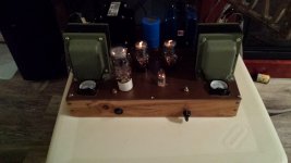
The voltages around the 12AT7 look really wrong.
4,5, and 9 - 30 volts? Not sure how you are measuring it, but that's not right. You should have 6 to 7 volts AC across pin 9 and pin 4, and pin 9 and pin 5.
1 is the plate of section 1 - not likely to work at all with only 210 volts on it, in my experience.
3 is the cathode of section 1 - it should have approx 1.8 to 2.1 volts dc measured with reference to ground.
6 is the plate of section 2 - not likely to work at all with only 88 volts on it, in my experience. Pins 1 and 6 need to be above 300 volts dc measured with reference to ground.
8 is the cathode of section 2 - it should have approx 1.8 to 2.1 volts dc measured with reference to ground.
The voltages at your coupling caps are wrong - but that's predictable because the voltages at the 12AT7 are all wrong; except for the 5 volts dc on the cold end of the right cap. It should not be there, but the cathode voltages otherwise look OK for that power tube.
Do you have genuine 10M45 CCS chips? Have you checked to make sure they are oriented correctly, and that you have the correct resistor values associated with them - measure them with one end lifted from the board.
What test equipment do you have?
Win W5JAG
edit: I was interrupted in making this post by several telephone calls, and we cross posted - yes, you should look really hard at the CCS on both sides.
Last edited:
This is a long shot, and probably not the issue - but your CCS heatsinks are not installed properly - they need to be rotated 180 degrees in either direction, so that the full surface of the CCS chip is in contact to the heatsink.
I don't know if these chips have a thermal shutdown or not; but at 9-10 ma and high voltages, they get warm enough to need the heat sink. I've found at lower currents and voltages ( 5 to 6 ma, 250 volts or less ) they are cool enough to not require a heat sink.
The CCS chips may be heat damaged, or thermally shutting down. Long shot, and probably not the problem, but they should be reoriented and it will take less than a minute to do it.
Win W5JAG
W5jag, I am following George's advice and using dcv. From his post I went thru and recorded as he suggested I should.
The 10 k feeding the CCS have checked out, in fact I've checked entire board 4 times pouring over every resistor and cap. That was reason for PCB photo I was verifying values and placement.
After performing the checks as per George, the CCS stuck out as it does not seem to be allowing the 285-300dcv out. The other CCS is working fine and has values of near 300 dcv.
I've ordered the CCS chip, will swap it out and re evaluate from there.
Thank you for help, I will be needing it!!
All the best
4,5, and 9 - 30 volts? Not sure how you are measuring it, but that's not right.
30 volts is about right. All heaters are elevated to 30 VDC to reduce hum due to HK leakage.
If there is 480 volts on one end of R14 and 385 on the other, then roughly 10 mA are flowing through it, and that CCS is working.
1 is the plate of section 1 - not likely to work at all with only 210 volts on it, in my experience.
Only 210 volts, much more and it will melt. Sounds about right. 300 volts and 10 mA puts 3 watts through a 2.5 watt plate.
R24 however has only 36 volts across it indicating that only 3.6 mA are flowing. That's probably why there is only 88 volts on pin 6. Either R23 or R29 is bad or wrong. There was an error in an early version of the parts list. Both resistors should NOT be 1K, one of them is 330 ohms. I can't look it up right now since I am leaving on my road trip in a few hours.
R 23
Well I had to dig out my tubelab file, in it contained the schematic, it revealed that r23 is indeed 330ohm. Swapped it out and re measured.... Both channels read very similar dcv.
Happy I am. I connected my 6ohm speskers,music source and .......
Sweet music to my ears. Though not loud and a little distorted ( opt's are 8ohm) it works.
Thank you George and w5jag your help was invaluable!!!!!!!!
I will look to aquire some 8ohm speakers to allow for some serious tunes.
Thanks again.
Oh and George, any more thought into a phono stage? Your design would be awesome!!!
Cbeers
Grrr again
Well as time allowed I managed to connect a set of 8ohm speakers, the result was distortion,
Was using an I phone to pump some tunes and some music came thru how ever mostly distorted. I'm gonna try to go back in,as time permits and take my time to examine every thing.
All suggestions welcome.
Thank you to all.
Update
Hi all, After some time spent on this forum and critical analysis of the amp I solved it.
I have discovered that the volt meters I had installed were impeding the signal flow.
I temporarily disconnected them. Re tested the amp and it works and sound way better distortion free and loud.
Now one concern I have and it is the same in my first see the right channel seems to run at a lower volume then the left. ( When possible I've been adjusting balance thru player) to compensate.
Has anyone else noticed this, After all the recent checks I've done, pouring over schematic and parts, nothing is jumping out at me. Any clues?
Thanks.
- Status
- This old topic is closed. If you want to reopen this topic, contact a moderator using the "Report Post" button.
- Home
- More Vendors...
- Tubelab
- PT Help.


