Hi all,
Had an issue earlier this year where my Simple SE went dead and it has been operating just fine since I removed the SS rectifiers. At the time I noticed a cracked bias resistor, so I ordered a replacement for it and put it in later on.
Everything has been working smoothly until earlier today when we noticed a burning smell in the room. After isolating the oven, which was on - I realized it was the amp!
I immediately powered it off, but figured that a strong smell couldn't be good. As far as I could tell, the tubes were lit normally and there was no abnormal sound from the output. The amp was actually idle at the time we noticed the smell.
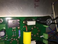
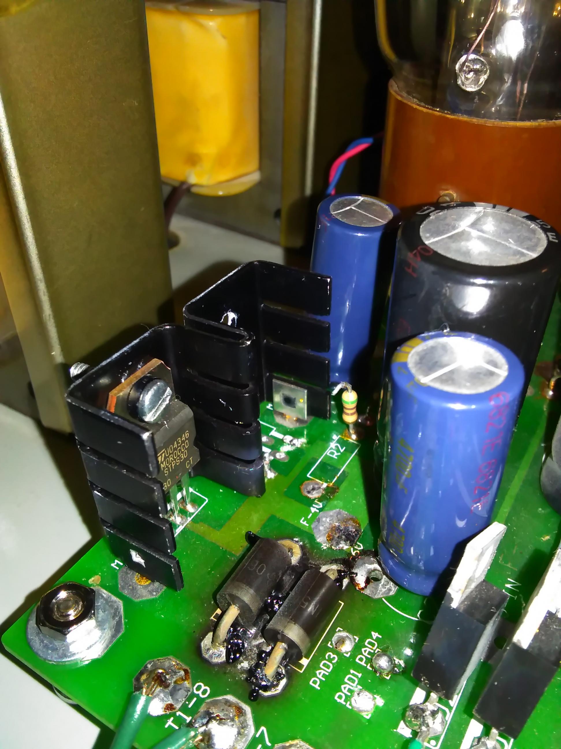
Removing the bottom panel, I see a blistered spot on the PCB right beneath the bias resistor that I had NOT replaced. There is adequate ventilation space between it and the PCB. Photo is attached of the carnage.
I removed both bias resistors from the circuit to measure. Across the resistor in question I measured 603 ohms which seems to still be in proper spec. However, the casing is cracked and came apart in my hand. The "new" resistor on the other tube measured more in the ballpark of 1.1k ohms. When I installed it, the values were very close to each other, so it looks like a defect with this new resistor drifting over the last maybe 6-9 months or so. It doubled in value?!
Obviously I've replaced both resistors due to their abnormalities. I am presently testing the amp under close watch. No strange behavior, strong smells, glowing so far. There is a faint smell right in the vicinity of the amp, but I'm wondering if heating the burned board will have some residual smell.
Music sounds great, as per usual.
I'm curious though, if there is any other explanation for this issue or anything I should verify as a result. Did the drifted resistor somehow cause a shuffle in the circuit which resulted in the normal side of the amp being driven too hard and overheating the other resistor? Is it possible something else is still bad and will cause further damage from continuing to operate the amp?
All tubes still have proper vacuum and there were no glowing plates observed at the time of said smell. No other parts or board spots show discoloration, bulging, cracking, or anything else out of the norm.
Possibly worth note - I've gone through a couple pairs of output tubes over the years. This amp gets a lot of use as the main source for both music and TV viewing. Normally run KT88 tubes, so I figure I should make sure I'm not driving things too heavily.
Thanks for any advice!
Had an issue earlier this year where my Simple SE went dead and it has been operating just fine since I removed the SS rectifiers. At the time I noticed a cracked bias resistor, so I ordered a replacement for it and put it in later on.
Everything has been working smoothly until earlier today when we noticed a burning smell in the room. After isolating the oven, which was on - I realized it was the amp!
I immediately powered it off, but figured that a strong smell couldn't be good. As far as I could tell, the tubes were lit normally and there was no abnormal sound from the output. The amp was actually idle at the time we noticed the smell.
Removing the bottom panel, I see a blistered spot on the PCB right beneath the bias resistor that I had NOT replaced. There is adequate ventilation space between it and the PCB. Photo is attached of the carnage.
I removed both bias resistors from the circuit to measure. Across the resistor in question I measured 603 ohms which seems to still be in proper spec. However, the casing is cracked and came apart in my hand. The "new" resistor on the other tube measured more in the ballpark of 1.1k ohms. When I installed it, the values were very close to each other, so it looks like a defect with this new resistor drifting over the last maybe 6-9 months or so. It doubled in value?!
Obviously I've replaced both resistors due to their abnormalities. I am presently testing the amp under close watch. No strange behavior, strong smells, glowing so far. There is a faint smell right in the vicinity of the amp, but I'm wondering if heating the burned board will have some residual smell.
Music sounds great, as per usual.
I'm curious though, if there is any other explanation for this issue or anything I should verify as a result. Did the drifted resistor somehow cause a shuffle in the circuit which resulted in the normal side of the amp being driven too hard and overheating the other resistor? Is it possible something else is still bad and will cause further damage from continuing to operate the amp?
All tubes still have proper vacuum and there were no glowing plates observed at the time of said smell. No other parts or board spots show discoloration, bulging, cracking, or anything else out of the norm.
Possibly worth note - I've gone through a couple pairs of output tubes over the years. This amp gets a lot of use as the main source for both music and TV viewing. Normally run KT88 tubes, so I figure I should make sure I'm not driving things too heavily.
Thanks for any advice!
Attachments
Just an update - the amplifier seems to operate as per usual. Everything sounds great.
The problem is that the bad smell does come back, and I'm not really sure if it is as strong as last time but I didn't let it run as long as the last time the amp was in operation because I figure this can't be good.
Definitely hoping I can get this figured out before New Year's Eve as we always have a big party, and it would be a shame to have a substitute amp. Thanks in advance!
Are you qualified to *safely* measure the operating voltage on that resistor?
The docs suggest it should be near 39V.
If the 200K grid resistor is not connected, or the grid capacitor feeding them is leaking, the voltage and tube current may be much higher.
39V in 560 Ohms is 2.7 Watts. High for a "5W" resistor but should not be giving this much trouble. 603 Ohms would be a hair cooler. So something aint right.
.... There is a faint smell right in the vicinity of the amp, but I'm wondering if heating the burned board will have some residual smell.
When I set my TSE almost on fire with the SV-811's, my radio room stunk like a rotten potato fueled tire fire for many days afterward. It would not surprise me that your board is continuing to outgas when it heats up. edit: The outgas will eventually stop; in the interim, maybe you can stand that power resistor on end, or relocate it away from directly under the burned spot.
Did the drifted resistor somehow cause a shuffle in the circuit which resulted in the normal side of the amp being driven too hard and overheating the other resistor? ....
It is possible, I guess, if everything was running on the ragged edge to start with, that one side drawing a lot less current allowed the B+ to creep up enough to cause the other side to draw more current and overheat. No real way to know without duplicating the original condition and taking some measurements.
Is it possible something else is still bad and will cause further damage from continuing to operate the amp?
Poor ventilation under the chassis would seem like a reasonable suspect. Bad power tubes are another possibility; you might want to make sure the coupling caps are not leaking.
This amp gets a lot of use as the main source for both music and TV viewing. Normally run KT88 tubes, so I figure I should make sure I'm not driving things too heavily.
My CR SSE does similar duty - often 18 to 24 hours / day. One of my boards went tens of thousands of hours that way. That board is now hacked to make a DH style SSE, and could face many more thousands of hours of abuse. As long as you have allowed for suitable heat dissipation, duty cycle is a non issue, imo.
Win W5JAG
Last edited:
Firstly I have 2 SE PCBs and have not built them yet, and have been reading along for hints and tips. I am from an electronic background,
If a PCB has become charcoal, it is bet to remove the charcoal. It is conductive. You can drill it out or scrape it out, Then fill in the board with clear electrical varnish. Monitor its performance. (I would consider buying a new PCB anyway for longer term benefit and rebuild it with lessons learnt)
As for the fault. I do not know what has caused it , sorry.
When I build mine I may end up mounting heat generating components further off the board, and use the metal encased high wattage resistors and mount them on a heatsink.
I have repaired a few guitar amps that have PCBs that have been burnt. Cutting the charcoal cured the symptom, but usually new output tubes were also installed at the same time. (tubes were in for 20 years)
Mr Tubelab however will always have the best answer
...
If a PCB has become charcoal, it is bet to remove the charcoal. It is conductive. You can drill it out or scrape it out, Then fill in the board with clear electrical varnish. .....
OP's board looks discolored at worst, and the voltages in that area are slight. I wouldn't worry about any long term effects on the board.
This is much more significant damage, done a bit more than a year ago, in a part of a TSE board that has low voltage:
http://www.diyaudio.com/forums/atta...-tubelab-single-ended-img_20151218_203045.jpg
http://www.diyaudio.com/forums/atta...lab-single-ended-wp_20151219_11_39_13_pro.jpg
http://www.diyaudio.com/forums/atta...-tubelab-single-ended-img_20160110_145304.jpg
After replacement of the 1N5401 friodes, which run quite hot, this board has functioned fine for a year without making any attempt to insulate or isolate the carbon residue. I have some corona dope, but I have not seen any evidence that it is required here.
Win W5JAG
Last edited:
WOW, had a look at those pics of the greater damage. I am surprised if they are no issue. But hey if it works it works. I personally would not run it while not in the room.
Most PCBs that I have worked on that are like that amount of damaged are scrapped. (non tube PCBs) payphone power supplies (24V to 48V) and bus ticketing machines(24V). Especially when the pcb has crumbled. If we put them back in service (last option if boards are obsolete) we have to remove all residue and use clear varnish, and note it is the service record. If there are signs of some sort of runaway we would have try again.
I have found the charcoal is not always immediately conductive/fault causing, sometime it can take a few mins. Other times it can take months.
I have seen a ticket machine catch fire at the site of the charcoal with my own eyes. A technician replaced the already faulty components, but neglected to remove the burnt PCB, and it was not as bad as that PCB in the pics. From that moment on he always removed the charcoal.
Poor ventilation under the chassis would seem like a reasonable suspect. Bad power tubes are another possibility
My "industrial" SSE should be the poster child for poor ventilation. It was built on a chassis that barely fit all the parts with a shoehorn. Then I put EH KT88's in it and cranked the current up to about 100 mA. That's 220 mA sucked out of a 175 mA Hammond power transformer. You can't tough it after a few hours of use. It was the amp between my computer and the Yamaha NS-10M's for about 4 years, so it ran most of the time I was home. It also popped the diodes during a Florida lightning storm so I just cut them out. Other than that the amp is still like it was built (same tubes even) 8 years ago......sadly it was dropped during a move and doesn't look quite right any more.
The board had discolored slightly under the resistors, but not like yours. Clearly, as stated, something isn't right.
One oddity is the 1.1K reading on one of the resistors. I have abused these white ceramic and sand resistors (mostly Xicon's from Mouser) and they usually work fine, and go completely open when they blow. I have abused them continuously up to and beyond the 5 watt spec without seeing one crack. It usually takes about 10 watts to blow one, and they will discolor and possibly blacken or char a PCB at this power. My guess is that the resistor is open and you are measuring 1.1 K through a compromised bypass cap, but you say the amp works.
As stated, it is possible, and not uncommon for an output tube to work fine for years, then suddenly go into red plate runaway. This is much more common on modern production Russian and Chinese tubes than on NOS stock. What happens is that over time impurities and "gas" contaminate the vacuum in the tube leading to excess grid current. Some of this grid current cancels the bias driving the cathode current up, which also raises the cathode voltage, putting a double whammy on the cathode resistor. It is not uncommon for the bias current to creep upward a few tenths of a volt per day with no other effects, until one day it skyrockets and blows parts. It is more common for distortion or hum to appear in the final hours / days before the big bang.
The amp was actually idle at the time we noticed the smell.
Idle is the worse case power dissipation for any class A amp. All SE amps by definition must be class A. At idle zero power is being supplied to the speakers, so every watt produced by the power supply is dissipated in the amp.
Does it smell like burnt PC board material, or a caustic chemical stink. The chemical stink comes from an electrolytic capacitor that has overheated and vented. Usually there is a sticky stinky goo evident near the cap. Usually a vented cap will split along the creases in the top, which I don't see here, but there is some vague white powdery substance on the top.
The guaranteed sure fire cure is to replace the resistors, the cathode bypass caps, and possibly the output tubes. If the voltage got high enough to shatter a resistor, it likely went over the max spec for the bypass cap (50 or 63 volts).
If the output tubes are not replaced, it would be wise to leave a meter connected across the cathode resistors and watch the cathode voltage. Check the voltage at idle, loud music will make the current vary. It should be in the 38 to 42 volt range and stay within a few tenths of a volt after the amp has been on for hours. If the voltage slowly creeps upward, another event may be in your future.
I had a KT88 that would runaway, then act normally for a while, often weeks, then do it again. It took me a while to see it. A faint blue glow would appear inside the plate structure, which would slowly get brighter, then there was a purple flash and a blown fuse.
As for the carbonized area, it should not be an electrical issue here, but effort to remove as much of the black stuff with an X-acto knife, Dremel tool or other means may reduce the smell. Yes I have seen carbonized PCB's that arc, or even burn far after the original issue was fixed, but these have been cases involving high voltage, moisture, or both. Worse case was Pepsi in a security guard's CRT security monitor. It took a bit of surgery to cut out all the toast, then rebuild all the missing traces, but I got it fixed before the boss came in.
Scrape away as much of the black stuff as possible without damaging any of the metal traces. then clean the area with alcohol or other suitable solvent, and make sure it is completely dry before powering it up. Ordinary rubbing alcohol contains water, some of which may be absorbed into the fiberglass, so make sure it is dried before use. A hair blow drier may be handy. I usually clean fried or gooey boards with WD40 but some people say this isn't a good idea.
Last edited:
I removed both bias resistors from the circuit to measure. Across the resistor in question I measured 603 ohms which seems to still be in proper spec. However, the casing is cracked and came apart in my hand. The "new" resistor on the other tube measured more in the ballpark of 1.1k ohms.
603 Ω is "within spec" but 1.1 kΩ is also within spec? That makes no sense. Those resistors are typically ±5 % tolerance. As far as I can tell from what's available online, it should be a 560 Ω resistor.
39 V across 560 Ω is 2.7 W. It'll definitely get hot but shouldn't be hot enough to char the board. Is it possible that you have a tube that's getting flaky and drawing more current?
I suggest replacing both resistors and measuring the voltages across them if you can do so safely. Make sure everything is within spec.
Tom
Well, the mystery continues?
I may not have been clear earlier - when I discovered the incorrect value resistor (definitely way out of spec) I pulled it out of circuit where the measurement was still incidentally the same. I replaced it due to this reason, and replaced the other due to the cracking. The off-value resistor was a recent replacement.
I started by taking some resistance measurements around the board earlier yesterday. Across the two channels everything looks symmetrical (no drifted components from side to side). Checking voltages shows some variation but not a ton. The side with the burn spot measures 40.5 V across the resistor. The side without the burn spot measures 44.0 V.
So, the dissipation is below 3.5 W on the side without the burn, below 3 W on the side with.
Due to a party last night for New Year's Eve I decided to run the amp again, keeping watch on it. There is still some residual smell, but the amp does operate properly as far as I can tell.
The smell is definitely burnt PC board material, I've had caps blow in the past and that smell is most certainly different. None of the caps look remotely bulged, but I could replace the bypass cap if it would be good measure. I can also take more measurements if that would be advised, and could attach a meter hooked via clip leads for observation.
The bottom of the amp enclosure has numerous ventilation holes. The top has enlarged rings around the tubes for airflow and there is convective motion felt when the amp is operating. Is this enough? That I'm not 100% certain about - the bottleneck would be the top side, but again wouldn't I be seeing more (or at least symmetrical) problems?
The only time I've had blown caps so far is during tube runaway incidents which were either massively noticeable due to operative problems or red plates, or catastrophic causing blown fuses.
Thanks so much for all of the responses! One of the lessons I've learned here is that I need a backup chassis of some kind!
If you decide to repackage the amp, or maybe in your current package, see if there is room to mount the 5 watt resistors between the board and the top plate without them contacting the PCB. If so position the resistors such that they will be in constant contact with the plate, smooth side touching the plate. Apply a layer of thermal paste on the top of the resistors, the kind used by computer builders on the CPU chip. "Artic Silver" or other paste with fine powdered metal in it is preferred.
I put the resistors through the PCB holes, but did not solder them. Then I mounted the PCB to the plate. Then I worked the resistor leads such that the resistor had a firm flat contact with the top plate. Then I soldered each resistor.
This allows the top plate to act as a heat sink for the resistors and keeps the heat from the resistors from cooking the PCB.
I had forgotten that I did this on my original industrial amp, but I remembered when I looked over its mangled remains on the shelf while fetching the PCB from another dead amp.
I'm revisiting this post as I miss the amplifier (threw a halfway decent bookshelf EL84 amp I had in its place, but the sound quality and bass aren't the same).
If I flip the resistors to the other side of the board and scrape away all the char, do you think things will be OK, or should I consider replacing the PCB as well? The scent never went away before I subbed the other amp in place.
If I flip the resistors to the other side of the board and scrape away all the char, do you think things will be OK, or should I consider replacing the PCB as well? The scent never went away before I subbed the other amp in place.
Wow, far too much time has passed - I am reviving this thread as I am putting the finishing touches on a new circuit board. Just waiting for a few final parts to arrive. Once the original is out, I may try to recover it for future use.
What I want to do before I get carried away is make sure things will be good for the long haul. I'm open to suggestions on chassis modifications that would improve the health of the board and components underneath. I'll have to post a photo here for everyone to get an idea, but the board is beneath a thick aluminum top plate attached to a wooden chassis. There are many holes in the underside protective cover, and there are enlarged holes around the tube sockets. Transformers are mounted topside, the choke underneath, and the big motor capacitor underneath. I'm wondering if I need increased ventilation.
I'm also curious since I'm using the Edcor power transformer (XPWR033 - 760VCT @ 200mA, 6.3V (No CT) @ 5A, 5V @ 3A) if I am pushing the amplifier too hard due to the variation in spec. Also, is the bias resistor appropriate for 6550 / KT88 output tubes or should I not be pushing them so hard? I've had a few tubes fail over the years and am still trying to figure out the ideal operating conditions.
I also see the new revision of the SSE board has two extra diode locations (D3 and D4) and also TR1. Curious to know more about these parts, as I didn't notice an update in the documentation for them.
I was thinking about installing SS diodes for occasional use, but I noticed that now not only are the originals NLA, but the RHRP15120 is also backordered everywhere. Is there possibly another new replacement for them?
Finally, regarding the resistors, I intend to mount them to the plate. I presume if they are closer to the board than they were on the bottom side, mounting in this way will still be better since the top plate will dissipate most of the heat upward. Are there any good thermal pastes sold at the parts distributors, or should I pick up the Arctic silver elsewhere?
TIA for any help that can be provided... I'm really excited to have it playing again, especially with the holidays coming up.
In what is now 3 SSE builds, for D3/D4 I ordered the following from DigiKey which are currently in stock:
UF4007-E3/54GICT-ND, DIODE GEN PURP 1KV 1A DO204AL
My first build runs at least 10 to 12 hours daily for the past 2 years. I'm running the Edcor XPWR035 in all of them which is a few volts shy of yours but no heat issues to report.
Hope that helps.
UF4007-E3/54GICT-ND, DIODE GEN PURP 1KV 1A DO204AL
My first build runs at least 10 to 12 hours daily for the past 2 years. I'm running the Edcor XPWR035 in all of them which is a few volts shy of yours but no heat issues to report.
Hope that helps.
Hannibal 8 - Thanks for the information! How is the ventilation in your various amps' chassis?
Also, curiously do you have any hum from the Edcor PTs during operation? I suppose I should ask what tubes are you running, since that will affect bias and current draw when comparing. This seems especially curious to me, given the XPWR033 has a lower current 5V tap used by the rectifier and I recall my own amp being more quiet with SS rectification than with the tube (as long as the tube was removed and not drawing filament current).
I often run my amp a substantial amount of time, most of the time it is also daily. I've had it now for almost 10 years. Crazy to think that looking back. I've been through at least four sets of power tubes (if the present 6550's are still good). One set was defective and I eventually got warranty replacements which I may put into service since they are new (PSVANE T-II). They sounded awesome when they were running.
The existing tubes which were running just fine in spite of the charred board were a set of Tung-Sol 6550 plus a matching TS 12AT7 and TS 5AR4. They also give the amp a very nice sound.
I patterned the top plate of my chassis after MetaRuss's build that I saw links from this site. I didn't have the tools to cut perfectly sized holes for the tube sockets so these are oversized with a smaller plate painted black that is recessed a bit. I thought it looked sharp and it probably does help with airflow.
I have a set of JJ EL34, 6L6GC and KT88's I bought with the intent of collecting more but really haven't expanded past that.
The first amp had a very slight hum that I never felt compelled to track down or spend any time chasing after trying to fix. Amp #2 was a gift and I powered it up and it sounded okay and that was that. Amp #3 is dead quiet but I spent more time paying attention to keeping my wiring neat and tidy on that one.
I built these for fun with little electronics experience. I keep wanting to learn more about circuitry and theory but life keeps getting in the way. I just followed directions and used quality materials and they amazingly worked when I powered them up and sound fantastic.
Well, it sounds like my top plate and ventilation is probably on-par with both of yours. My enclosure is actually larger, so I don't have much concern there either. And the daily run time on my amp is less, for what that is worth. Looking at other enclosure pictures, I feel a bit more confident that it hasn't played too much of a factor here.
Regarding the diodes and that other component which I didn't find information for (TR1), is there an explanation somewhere of their purpose? I seem to recall a thread discussing the use of diodes to help extend the rectifier tube's life at some point. That is my guess for their purpose. Are there any modifications that are needed to use / not use them?
I feel like there would be a changelog somewhere but I haven't found it here or on George's site yet.
Last edited:
Ok, after digging I found some answers... should have searched a bit longer:
http://www.diyaudio.com/forums/tubelab/216689-starting-sse-build.html#post3103376
So my question changes a bit as a result - I'll definitely be installing the diodes to soften power-up effects on the rectifier. When I built my amplifier long ago, I was already thinking about the potential for inrush current, and I put a CL80 device in the amp, though it is in-line with the hot lead that enters from the IEC jack to the power switch. I'm curious if there is an advantage to removing it and using the new board mounted location instead? Does it allow the rest of the amp to come to full voltage faster than the B+, somewhat like a standby switch would?
Regardless, I now have a tally of the parts I didn't purchase on the first go around, so I can get my last order on its way and finish building the board.
Last edited:
- Status
- This old topic is closed. If you want to reopen this topic, contact a moderator using the "Report Post" button.
- Home
- More Vendors...
- Tubelab
- Tubelab SSE Board Damage - Help!