I was able to acquire 4 of these CV345 nos tubes for cheap. I looked them up and while not a drop in substitute for el34's they have been used in amps by running a lead from pin 3 to the top cap. Some people online have raved about these tubes. Not knowing enough about how tubes are chosen for a particular design I thought I'd ask here. I am building a tubelab SSE and have been collecting various tubes to use in this amp.
I guess my question would be has anyone used these and if so what changes are deemed mandatory or just suggestions if I were to run them in a sse?
Sent from my SM-T810 using Tapatalk
I guess my question would be has anyone used these and if so what changes are deemed mandatory or just suggestions if I were to run them in a sse?
Sent from my SM-T810 using Tapatalk
The CV345 or 12E1 tube has the same pin out as the KT88 except on the KT88 pin 3 is the plate (anode) whereas on the CV345 the plate is connected to the top cap.
For use in the SSE you would have to use an adapter socket to connect pin 3 to the top cap on the CV345.
While the maximum plate voltage rating on the CV345 is 800V it is only 300V on the screen grid so you'll have pay attention to that.
For the cathode bias resistor you'll have to experiment with that. Using a rotary selector switch you can parallel several
different resistor values with the main on board resistor to achieve several different cathode resistor values.
If you read through this thread you can get some ideas on how to do this.
Howdy fellas, I've some simple SE questions...
I haven't used the CV345 so I don't have any experience with them.
Thanks for the info, I am aware of the pin3 mod, and the difference in grid voltage. Does anyone know off hand what the grid voltage is on the Sse?
That thread was very helpful and I think I may make that rotary resister modification. It makes biasing for different tubes easy. Though I may go for a 5w potentiometer instead of resisters. Anyone have any idea what the value should be? Ie 500ohm 1k, 5k, 50k, etc? I'm still new to this stuff! LOL
I'd like to make my sse as flexible as possible because I want to be able to use as many tubes and values as possible so I can find the sound I like best. And of course learn as much as I can while doing so.
Also does anyone know how to make b+ adjustable? I see in the "man cave build" he was able to include a attenuator circuit. Am I correct in assuming this circuit just limits the b+ by adding resistance? Anyone have a clue? I asked in the thread but the owner has not been online here for a number of months.
Sent from my SM-T810 using Tapatalk
Sent from my SM-T810 using Tapatalk
The control grid and screen grid are different electrodes in the tube, and do very different functions.
The best plan, imho, is to build out your SSE completely stock with a common tube like a 6L6GC, and when it is known to be working properly, then consider the use of oddball tubes, like your 12E1's.
If the 300 volt rating on the screen grid is accurate, that dictates how the tube would be used on the SSE. Some screen grid ratings can be fudged, some can't. Not trying to be cryptic, but tubes with low screen grid ratings can kill some parts, like cathode bypass caps, pretty fast. It sounds like 12E1 is somewhat similar to 6DQ6 and 6BQ6, right down to the pin out. Searching on these type tubes fitted to the SSE should give you some insight into the issues involved.
Win W5JAG
Thanks for pointing out the different grids, that slipped by me. Still trying to get it all straight in my head.
Building a stock sse and then modifying it was my plan from the start, it helps keep troubleshooting relatively uncomplicated. Mostly I am planning ahead to what modifications I want to make later on. I have populated my board but waiting for my transformers from Edcore to come, so building and bench testing are on hold. All I can do now is plan.......lol
Building a stock sse and then modifying it was my plan from the start, it helps keep troubleshooting relatively uncomplicated. Mostly I am planning ahead to what modifications I want to make later on. I have populated my board but waiting for my transformers from Edcore to come, so building and bench testing are on hold. All I can do now is plan.......lol
Bump
Trying to resurrect this thread, my sse is functioning in basic mode, ul, and with cfb. I've rolled a bunch of compatible tubes and all work.
I'd really like to learn what modifications are necessary to use this tube in my amp. It's a CV345 also known as 12e1. It is pin compatible with a wire from pin 3 to the topcap.
12E1 pdf file
Any help from the more experienced builders that have the patience to help a noob would be greatly appreciated.
I understand it's a tetrode and has a 300v limit on screen grid. Can anyone explain why this would cause problems? In a previous post I was told it could cause issues with other parts like cathode bypass caps?
Any time you go out of the parameters the designer intended, you have to be prepared to experiment and live with the consequences, good or bad. Some work. Some don't, spectacularly.
I don't know anything about 12E1 - it looks like it might have been intended as a pass element in regulated power supplies. I couldn't get your data sheet to download, so I downloaded the attached sheet.
Looking at the last pages for a triode connected tube, it looks like the bias voltage gets really high - they don't bother charting it past 300 volts on the plate. The SSE is cathode biased - the negative grid voltage is derived from the voltage drop across the cathode resistor. If your SSE has a typical plate voltage of 450 ish volts, just dropping this tube in without more could make a cathode voltage of 70 volts or higher, and your current may well be more than 100 ma / tube, or more than 40 watts / tube.
What is the voltage rating on your cathode bypass capacitor? 63 volts? This is why tubes like this can explode the bypass capacitor fast. You probably need a significantly higher cathode resistance than presently installed, which will make the voltage drop even larger, thus an even higher voltage bypass capacitor is needed.
I use weasel words like could, looks, and probably, because apparently no one has done this on an SSE and you will be blazing ( hopefully no pun intended ) a new trail.
If it were me, and I make lots of mistakes, some expensive and painful, I would approach this tube with caution - I would try it as a triode; I would use a rectifier like 5R4 to minimize the plate ( and screen - since they're tied together ) voltage; a 100 volt bypass capacitor; and I would probably start with a cathode resistor of about 820 ohms, 10 watts, with meters on everything to see where I was at. Once you get a feel for what this tube does, you can go on from there.
The mu is kinda low, it will need more drive, might not sound as loud.
Just my $0.02. Others may have different ideas.
Win W5JAG
Attachments
I'm using a phone so l can't go into the details now but this tube will likely blow the cathode bypass cap and possibly the resistor. The 6BQ6 and 6DQ6 also share the same pinout.The 6BQ6 can be made to work, but no so well. The 6DQ6 blew my board. This tube looks more like a 6DQ6.
Any time you go out of the parameters the designer intended, you have to be prepared to experiment and live with the consequences, good or bad. Some work. Some don't, spectacularly.
I don't know anything about 12E1 - it looks like it might have been intended as a pass element in regulated power supplies. I couldn't get your data sheet to download, so I downloaded the attached sheet.
Looking at the last pages for a triode connected tube, it looks like the bias voltage gets really high - they don't bother charting it past 300 volts on the plate. The SSE is cathode biased - the negative grid voltage is derived from the voltage drop across the cathode resistor. If your SSE has a typical plate voltage of 450 ish volts, just dropping this tube in without more could make a cathode voltage of 70 volts or higher, and your current may well be more than 100 ma / tube, or more than 40 watts / tube.
My B+ is 425v
What is the voltage rating on your cathode bypass capacitor? 63 volts? This is why tubes like this can explode the bypass capacitor fast. You probably need a significantly higher cathode resistance than presently installed, which will make the voltage drop even larger, thus an even higher voltage bypass capacitor is needed.
Not sure I'll have to look at the board as I bought parts and assembled the board 1.5 years ago with a major move in between. I only started testing this now as I finally found the transformers that were packed away recently. Lol
Perhaps it would be easier to experiment using a design that was made for this tube instead of the sse? I found one but being new to reading schematics i'm not certain its an audio amp cause it does use the crt from a oscilloscope in the design,I use weasel words like could, looks, and probably, because apparently no one has done this on an SSE and you will be blazing ( hopefully no pun intended ) a new trail.
If it were me, and I make lots of mistakes, some expensive and painful, I would approach this tube with caution - I would try it as a triode; I would use a rectifier like 5R4 to minimize the plate ( and screen - since they're tied together ) voltage; a 100 volt bypass capacitor; and I would probably start with a cathode resistor of about 820 ohms, 10 watts, with meters on everything to see where I was at. Once you get a feel for what this tube does, you can go on from there.
The mu is kinda low, it will need more drive, might not sound as loud.
Just my $0.02. Others may have different ideas.
Win W5JAG
Found this one on the Triode DIY homebrew amp page. Though searching for 12e1 schematics turned up more, I originally searched for CV345 as that is the boxes I have. I'll report back on bypass caps and cathode resisters shortly.
Attachments
I'm using a phone so l can't go into the details now but this tube will likely blow the cathode bypass cap and possibly the resistor. The 6BQ6 and 6DQ6 also share the same pinout.The 6BQ6 can be made to work, but no so well. The 6DQ6 blew my board. This tube looks more like a 6DQ6.
So I'm guessing it not as easy as replacing a few parts for this tube to work? Ah well as I said in my previous post perhaps using a circuit designed with this tube in mind is the way to go, in order to experiment. It would make me learn a bit more about design of tube gear by doing it this way, I just wish I had someone close to me that I could learn from as I'm better at learning from seeing and doing than reading and trying to do on my own. I do have a vtvm and an oscilloscope but very little experience using them! Lol
Well any insight would still be appreciated. Thanks
So I'm guessing it not as easy as replacing a few parts for this tube to work?
I am just guessing here, since I have never seen this type of tube, much less experimented with it, but I can say that it MAY be possible to get this tube to make some music in an SSE. It likely will not work as well as a 6L6GC, and the possibility of success without some more knowledge and test capability is near zero. How do I know this?
I started out tinkering with tube stuff in the 1960's. I had an electric guitar and my amplifier was al old mono Magnavox console HiFi that I got when my parents upgraded to stereo. I wanted to make a better guitar amp, but had zero budget. In the 60's you could go to the trash dump and pick through old TV sets, radios and Hifi's for the tubes, transformers, and other parts.
I traced out the schematic of an old Fender Champ borrowed from a friend, and managed to make my own from trash parts. What comes next? Well I wanted to make it bigger and louder, so I tried stuffing in bigger tubes. Anything with a similar pinout got tested. Sticking a 6L6 into the 6V6 socket made it a little louder, but not what I had expected. Bigger tubes like the previously mentioned 6BQ6 and 6DQ6 actually lost volume, and the 6DQ6 made my output transformer start smoking. It didn't make sense to me why a bigger tube was less loud than the smaller tubes, but I kept on experimenting, and blew up quite a few parts along the way. I was a 10 year old kid with no clue about bias, maximum voltage ratings, current, impedance, load lines, and other important concepts, and there was no internet to look stuff up on. I would pick up bits and pieces from books and talking to a local ham radio guy, but I really didn't understand the basics until I got into a technical high school electronics program a few years later.
Fast forward about 40 years and I'm tinkering around with an SSE, and I remembered those old days.....OK, now that I understand, I'm going to stick that 6BQ6 and 6DQ6 into my SSE (same SE output stage as that guitar amp from 1963) and make them work, or blow something up trying.
Pentode and beam tetrode vacuum tubes have two main grids to regulate the current flow inside the tube. There is also a third grid for suppression of some unwanted characteristics. The control grid (G1) is used for primary current control and usually operated with a more negative voltage than the cathode. The screen grid (G2) acts as a shield between the control grid and the plate and serves to accelerate the electron stream towards the plate. Some tubes have a very sensitive screen grid and it usually operates at a low voltage in the 100 to 300 volt range. Some tubes have a less sensitive screen grid which usually operates at a voltage near or the same as the plate voltage. These tube types are usually NOT interchangeable, and bad things will happen if you stick a sensitive G2 type into a design made for a insensitive G2 tube.
The SSE, amplifier was designed to work with common audio power output tubes that have a rather insensitive screen grid. This allows the tubes to operate in triode or UL mode since both of these run G2 at or near the plate voltage.
Your 12E1's have a maximum screen voltage rating of 300 volts. Your B+ is probably in the range of 420 to 450 volts. The 12E1 isn't going to like this.
The SSE uses cathode bias, sometimes called automatic bias. G1 is grounded. There is a resistor and a bypass cap from the cathode to ground. Current through the tube goes through this cathode resistor causing its voltage to be several volts positive (25 to 45 volts in an SSE). This makes G1 more negative than the cathode. If the current through the tube rises, the cathode voltage rises causing the apparent G1 to cathode voltage to be even more negative, reducing the current through the tube.
Applying 430 volts to a screen grid designed for 300 volts maximum will cause a lot of current through the tube. This will develop a lot of voltage across the cathode resistor in an attempt to reduce this current. If this voltage is high enough, the cathode resistor, it's bypass cap, or both will die! Simply sticking in bigger parts may subject your tubes and transformers to more current than they were designed for causing damage...... this can get expensive quick.
Any time you go out of the parameters the designer intended, you have to be prepared to experiment and live with the consequences, good or bad. Some work. Some don't, spectacularly.
I ALWAYS experiment with expendable parts (especially transformers) until I am satisfied that stuff won't blow up. I use adjustable lab power supplies on everything so I can find out where I can ignore some ratings, and where I can't. I have been doing this for over 50 years, and I still blow stuff up!
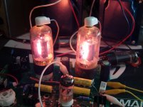
Back to the SSE with 6BQ6's. Those sensitive screen grids (175 volts max) really didn't like 450 volts. The tubes glowed like light bulbs....for a few minutes. I connected a variable power supply to the screen grid, and fed it 150 volts, and the tubes did work, but they needed more drive than the usual audio tubes, so you couldn't get full power from a CD player.
The bigger 6DQ6 caused the cathode voltage to rise into the 80 volt range leading to the death of the 63 volt bypass cap.
Perhaps it would be easier to experiment using a design that was made for this tube instead of the sse? I found one but being new to reading schematics i'm not certain its an audio amp cause it does use the crt from a oscilloscope in the design,
This IS an audio amp design. It also includes some type of crude oscilloscope to display something resembling audio. It however can't work right, if at all as it is drawn. A quick look shows two major mistakes. The connections from the amp to the oscilloscope have about 400 volts on them since they come from the plates of the output tubes. They connect to the wipers of the input pots on the "scope." Turning the input all the way down will short out the B+ really frying some parts. The design also puts the tone control INSIDE the feedback loop. This is a good way to make a very loud oscillator. It also violates the 300 volt screen grid rating of the 12E1. I doubt that this was ever built.
I agree that the 12E1's would be best used in some sort of push pull amplifier. They would probably make well over 50 watts per pair too.
Attachments
Ok thanks George for that great explanation, I think I'll pass on trying to stuff this tube into the sse. I did find a bunch of other designs after searching for 12e1 schematics so perhaps I'll look for one of those to play around with.
Yeah I'm old enough to remember tubes being mundane items in just about all households but too young to have been able to play with them until now. Trouble is I really need to find someone locally I can learn from. The internet is a great resource and I have purchased some books but without experience trying to design or play with unknown tubes is difficult if not impossible.
Well thanks again I'll look for another design I can work with and let you all know how it goes.From reading online these tubes are supposed to sound sweet, but it seems that to is a matter of taste.
If I was to look for a ready made design for those tubes I would look at Pete Millett's Engineers Amp. It was designed for tubes with a sensitive screen grid.
I got one of those boards and tried several dozen tubes in it, with good success. The board is laid out for 12 pin TV tubes, but different sockets can be rigged into it.
If you want to learn a bit, try reading the whole thread.....It's long and goes off in several directions including several of my experiments that squeezed as many as 525 watts out of Pete's 18 WPC design. Plenty of good information there.
Posted new P-P power amp design
If I was to look for a ready made design for those tubes I would look at Pete Millett's Engineers Amp. It was designed for tubes with a sensitive screen grid.
I got one of those boards and tried several dozen tubes in it, with good success. The board is laid out for 12 pin TV tubes, but different sockets can be rigged into it.
If you want to learn a bit, try reading the whole thread.....It's long and goes off in several directions including several of my experiments that squeezed as many as 525 watts out of Pete's 18 WPC design. Plenty of good information there.
Posted new P-P power amp design
Thanks George i'll give it a read. Thats actually funny because that engineers amp was on my list before i bought your boards, i think it came down to overall cost that made me not buy one at the time.
- Status
- This old topic is closed. If you want to reopen this topic, contact a moderator using the "Report Post" button.
- Home
- More Vendors...
- Tubelab
- CV345, 12E1 tubes anyone try these?