Hi All,
We're having problems with my son's SPP build and we hope someone here can help us figure it out. My son got the SPP board and populated the board per the instructions for UL mode. Wired it up with the transformers (Edcor) and such and powered it up through a dim bulb tester. Bulb lights up, then dims, good. After 20 seconds or so the bulb brightens again and the speakers produce a loud buzzing hum, which increases in volume as the bulb brightens. Of course at this time we shut it down to prevent damage to the amp, speakers, and our ears.
Any ideas? Suggestions?
Thanks!
Just finished my SPP 2 weeks ago and the first thing it did was howl at a lower frequency. I switched the transformer feedback leads and got a very high pitched scream so switched them back. When I disconnected the feedback the howl was gone.
I'm no expert so don't know why but my version of the amp seems to be very sensitive to the feedback capacitor size. If I use none or a very small value (max 100pF) then the amp is stable.
I'm no expert so don't know why but my version of the amp seems to be very sensitive to the feedback capacitor size. If I use none or a very small value (max 100pF) then the amp is stable.
Hi All,
Thanks for the replies. We did not install a feedback capacitor... if no feedback cap is used, should a jumper be used or just leave it open? Regardless, we tried the amp without the feedback loop, speakers connected directly to output transformers, and the volume was very low and distorted. We tried reconnecting with feedback, & reversing the right output transformer leads (we had originally had the output leads (white & yellow) connected identically to the right & left terminal blocks, but according to the diagram they're supposed to be reversed), but that ended up blowing the fuse (1A fast blow... will be switching to 1.5A slow blow).
This is actually our second attempt at getting this going. We had the same issues on our first attempt a couple of months ago. At that time on initial power-up with the dim bulb tester, we did not have speakers connected or a dummy load... we shut it down as soon as the bulb went bright again (about 20 seconds, IIRC), but we've since learned that running a tube amp without a load can damage the output transformers. Could that be what happened? How can we test the transformers to see if they're still good?
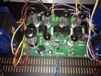
I've attached a photo of the top of the board, for what it's worth. We'll take the board out to check/photograph the bottom, but won't be able to get to that for a few days.
Thanks for the replies. We did not install a feedback capacitor... if no feedback cap is used, should a jumper be used or just leave it open? Regardless, we tried the amp without the feedback loop, speakers connected directly to output transformers, and the volume was very low and distorted. We tried reconnecting with feedback, & reversing the right output transformer leads (we had originally had the output leads (white & yellow) connected identically to the right & left terminal blocks, but according to the diagram they're supposed to be reversed), but that ended up blowing the fuse (1A fast blow... will be switching to 1.5A slow blow).
This is actually our second attempt at getting this going. We had the same issues on our first attempt a couple of months ago. At that time on initial power-up with the dim bulb tester, we did not have speakers connected or a dummy load... we shut it down as soon as the bulb went bright again (about 20 seconds, IIRC), but we've since learned that running a tube amp without a load can damage the output transformers. Could that be what happened? How can we test the transformers to see if they're still good?
I've attached a photo of the top of the board, for what it's worth. We'll take the board out to check/photograph the bottom, but won't be able to get to that for a few days.
Attachments
No jumper required if feedback capacitor removed.
I suggest trying the amp with the feedback wires from the transformer completely disconnected (and junk speakers connected). Install the the 1.5 amp slow blow fuse (2 amp slow blow is typical but you should be ok). With the bulb tester in use the sound should be there but it will be low and somewhat distorted.
It is normal for the bulb to go dim then brighten up somewhat again after switching on.
If everything looks ok plug it in directly and turn it on. After 30 sec or so you should start to get sound from the speakers. The amp should sound completely normal as it will work with no feedback.
If all the above works THEN start to work with the feedback.
Tried it on the lightbulb tester with no feedback, the bulb dimmed and then got brighter, continued anyways. Music played, no buzzing or anything. Just took it off the tester and the tubes glowed notably brighter and although there was no buzzing it started smoking. I believe R1 was the component that was smoking.
R1 is quite stressed in this design and will get hot but not sure it should smoke (unless it is burning off some manufacturing residue ??). If you are using El84 tubes it needs to be a 150 ohm 5watt resistor. The resistor in your photo seems small. I decided to not use R1 and rather installed a choke for this reason.
You could go over all the resistors by colour band to make sure they are correct and this is what I did on mine before applying power. If R1 has been stressed, and you are removing the board anyway, unsolder one side and check its resistance.
Also check for solder bridging. This in covered on the tubelab website in the manual under "getting started". Check both sides of the board:
Your power and output transformers appear to be hooked up correctly although a bit difficult to see in the photo.
You could go over all the resistors by colour band to make sure they are correct and this is what I did on mine before applying power. If R1 has been stressed, and you are removing the board anyway, unsolder one side and check its resistance.
Also check for solder bridging. This in covered on the tubelab website in the manual under "getting started". Check both sides of the board:
- R105 and R108
- R101 and V100 pin 8
- R103 and R104
- R203 and R204
- C205 and V202 pin 1
- C203 and V201 pin 1
Your power and output transformers appear to be hooked up correctly although a bit difficult to see in the photo.
After work today I'll check component values. R1 is correct, 150 ohm 5 watt. It strikes me as odd that even as the resistor was starting to smoke the amp sounded good with no odd distortion or anything. Also, I'm concerned about the tubes, they were glowing very very bright. Just how red should those el84s get?
My tubes glow but I would not say very very brightly. I have little experience on how bright a tube should be.
We are getting to the limits of my knowledge but it seems to me if resistors are smoking and tubes are too bright (and ALL of them are too bright) then your B+ is too high or the bias to all your tubes is off (which seems unlikely unless you installed all wrong bias resistor values).
I would check voltage at R1. Or even start by confirming that you have the correct voltages out of the transformer. If everything is normal then start with going over all the resistor values and look for solder bridges.
If you are unable to measure the voltage maybe you could post which power transformer you have. Would also be good to know which rectifier tube you have and now which choke you ordered.
The B+ voltage needs to be correct. I ended up measuring mine (a bit high with a Hammond 372HX 300-0-300) but was not happy or comfortable doing it!
Out of curiosity which output transformers do you have?
The B+ voltage needs to be correct. I ended up measuring mine (a bit high with a Hammond 372HX 300-0-300) but was not happy or comfortable doing it!
Out of curiosity which output transformers do you have?
- Status
- This old topic is closed. If you want to reopen this topic, contact a moderator using the "Report Post" button.
- Home
- More Vendors...
- Tubelab
- Help with SPP