....
Should I bump the coupling caps up to 0.2 or 0.3 uF from the existing 0.1 ?
In calculating the low pass cutoff, as the R value, do I use the value of the parallel combination of the load split and grid resistor, or just ignore the load split resistor, and use only the grid resistor?
It makes a difference - if my arithmetic is correct, the low pass cutoff is 49 Hz with the parallel resistance combination, or 7 Hz if I ignore the contribution of the load split resistor.
For a utility / test amp, paired with speakers and OPT's that don't go real low, I'm thinking a higher cutoff is better - also better overload recovery. Why use power for frequencies that the speaker won't reproduce? Am I missing something?
Win W5JAG
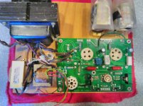
I've been giving some thought to a build out of the now modified ( butchered ) SSE board.
The power transformer I have in mind is a real space hog, but one of the things it has going for it is the inclusion of two 2.5V CT filament windings, it lacks a 6.3V winding, so I only net the elimination of one transformer. It is also 400-0-400, which is way overkill for these small tubes, but should be okay with a choke input, which I prefer, anyway. On the other hand, I've seen at least one circuit running 46's as triodes at 500 volts, so this transformer can accommodate experimenting with higher voltages.
At some point, I need to pick a team, and decide whether or not I want to use 46 and 47, or the more traditional 45 and 2A3. Picking that team has some other consequences - with 45 and 46, there are the extra grids that would allow pentode or ( maybe ) UL operation. I have plenty of tubes available, but am short on decent transformers for anything other than triode / pentode operation.
I have a self imposed constraint that a completed amplifier will have to fit a 12 x 10 chassis, and then fit under the existing cage that I already have for that size chassis. A further constraint is that the chassis height has to be the 2 inch variant, which only allows about 7 inches of vertical height to work within. A globe 46/47 is nominally 5 inches from the bottom of the base, to the top of the globe.
The idea here, which may or may not work, is that once a breadboard is finalized, and a decision is made to complete a usable amplifier, the chassis rear panel can then be precut, and the completed breadboard can simply be dropped into the inverted well of the chassis, and connections made from the prewired breadboard to the typical stuff on a rear panel - IEC, input, speaker, fuse, etc. The mounting holes for the chassis feet, would do double duty securing the breadboard to the bottom of the chassis. This should be rigid, and make the most of the available vertical height. Since all the tight stuff will have been done in advance on the breadboard, final completion should be easy.
I've cut a few breadboards, and have been playing around with parts layout. Smaller OPT's, such as the open frame Edcors, are not that big a problem. Larger ones, such as the Transcendars, which are vastly better performers, are tougher.
Win W5JAG
Attachments
Mule 2
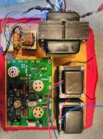
Mule 2, a directly heated SSE, is now up and running in breadboard form. I ran it about four hours continuously last night without any issues.
It's pretty barebones right now - LC power supply, 10 H Hammond choke, and a 220 uF cap. P-K voltage is 287; - 54 on the 45 grid, 13 watts Pd. 1200 ohm cathode resistor on the CT of the heater - it's a 5 watt type dissipating 2.5 watts, so it gets pretty hot; it's well above the board so hopefully will be OK. The bypass cap is 100 uF, I think, 35 volts, so we'll see how long that lasts before blowout. 5W4GT rectifier.
edit: I ran these numbers into SE Amp Cad, with a 7K load, and it predicts 2.1 % second harmonic, and 0.1% third harmonic, 970 mw output, IIRC. I think 5K increased second harmonic to about 2.8%. As of now, I have no means to actually measure THD.
The OPT's are a couple of cheapo's 5 and 7K primary; 4 and 8 ohm secondary. I expect these to be poor performers, but they should be uniformly poor for all types.
Other than checking some voltages, I haven't taken any measurements, yet.
Hum - surprisingly, not much. I have to put my ear up against the test speaker to hear any, and it's very low, at that. I have no idea what the sensitivity of the test speaker is. It's a 4 inch full range in a small cabinet, from decades before sensitivity interested me.
The filament supply for the 12AT7 is unchanged from stock, it's AC and floated as a normal SSE would be. The power tubes are at AC, with no hum balance pot. The open frame OPT's are in the plane of the field ( if any ) of the PT instead of the normal 90 degree cross. The filter cap is pretty small. Since I can hear the hum, I should be able to measure it, and then determine what difference, if any, adding a hum pot, bigger filter cap, reorienting the OPT's, etc., makes, if any. It may be an inconsequential amount, as is.
I still haven't picked a team, and am not really in any hurry to do so. Subject to change, but I thought I would try to characterize all of the small tubes, 45, 46, 47, 2A3 under varying conditions on the modified board, maybe 307A, and then with some data to make an informed choice, I'll probably toss a coin, or something, to decide on a tube for an actual build out, if I go that far. I don't need another amp.
It should be pretty easy to get in and out of the board with the barrier strips for the OPTS on the board, and the terminal blocks for OPT's, so hopefully this will be a useful mule for test purposes.
Fixed bias will be added later. I'm less sure about putting dc on the 12AT7 - I doubt that would make much difference. I am still interested in making some MOSFET modules to sit in the coupling cap position. By that point, it's starting to approach the complexity of the TSE, which defeats the whole point of modifying the SSE to make a simple DHT or dh UL or pentode amp.
Win W5JAG
Attachments
Last edited:
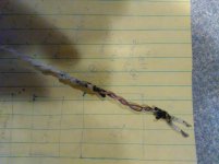
.... The bypass cap is 100 uF, I think, 35 volts, so we'll see how long that lasts before blowout. ....
About five hours.
But, that wasn't the real excitement - after changing the cap, on first power up, the twisted pair going to the filament went up in smoke. Literally. The wire is teflon insulated, so it didn't catch on fire, but within a second, it was dripping big globs of molten teflon, smoking like Hades, and the exposed wire was lit up like an incandescent lamp. Hard to tell from the pictures, but that remaining teflon insulation is fused together into one solid piece, all the way to the end of the run. The little black freckles on the breadboard are flecks of charred insulation.
That secondary is capable of 15 (!) amps, and it put all of that and then some into that wire.
Spectacular.
Absolutely no idea what caused this - no remaining evidence. Cut another pair, installed it, checked resistances, powered it up, and it worked fine. I did have the first pair twisted pretty tight, maybe 4-4.25 turns/inch. I relaxed the replacement a bit in an abundance of caution, but, that's really just a guess.
Win W5JAG
Attachments
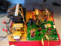
About 85 years young, and still working for a living.
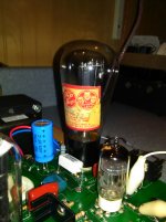
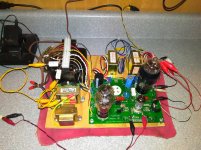
Type 47 in Pentode already looks to be an excellent choice for a directly heated SSE. The white clip lead is for a temporary plate to plate (Schade) local feedback loop. Oft criticized, nevertheless, it works quite well here, as it did in prior iterations of this board running 6146B, 6CD6, and other types in pentode.
With a 5K Transcendar OPT, the first iteration of this showed less than 1% SMPTE IMD at normal listening levels with high sensitivity speakers, about 3% at 500 mw, and about 7.5% at 1 watt. I didn't check it for power output, but I expect better than 2 watts clean sine wave. The high gain of the 47 is useful here. I could build an amp straight from this without changing a thing, and be well pleased with it. It sounded excellent on the test speaker - clean when it needed to be, raucous when necessary.
The picture does not show, but in the dark, the whole bulb of this 47 is bathed in blue glow. The 47 data sheet even mentions this is not a defect, so perhaps there is some peculiar characteristic of 47 that causes this. I'm totally OK with that.
I've abandoned those dual impedance transformers - they're just terrible. Useful as test transformers to get something working, but not much else. I don't think any data that comes from them will be useful in any way. They were represented as single ended, but I doubt they have an air gap. Maybe they can be used as chokes, or maybe at very low plate currents, or maybe they can be disassembled to try to make a gap, or paper weights here at the office; but they ain't useful for this test mule.
Win W5JAG
Attachments
Hmmm, fiddling around for an hour or so this morning, type 45 also responds well to the local plate to plate (grid ) Schade feedback loop.
It doesn't perform quite as well as the 47 below about 500 mw, but is very similar between 500 mw and 1 watt. The difference is small, and could be nothing more than the margin of error with my mediocre test equipment. I didn't listen to 45, or test it for output. It measured good, so it should sound good.
Win W5JAG
Here is the first set of data, in a text file because I'm lazy. Hopefully, my abbreviations and formatting can be made sense of.
The numbers speak for themselves, but a few random observations: all the tubes are running a bit hot, I haven't tried to dial them in. The 47 in pentode was with a 12AU7 - it measures better with a 12AT7, but has so much amplification factor, that I used a 12AU7 here to tame it a bit. The 100K feedback resistor is arbitrary. It may be right, or may be too much. I didn't test for sine wave max power.
The numbers speak for themselves, but a few random observations: all the tubes are running a bit hot, I haven't tried to dial them in. The 47 in pentode was with a 12AU7 - it measures better with a 12AT7, but has so much amplification factor, that I used a 12AU7 here to tame it a bit. The 100K feedback resistor is arbitrary. It may be right, or may be too much. I didn't test for sine wave max power.
Attachments
Some slight forward movement on this.
I pulled the Edcor XSE15 5K transformers from the CR SSE, and replaced them with a pair of teensy Merit A 2930's, to have a UL transformer available to experiment with for this endeavor.
Using the Edcor here runs into the same problem it faces on the CR SSE ( and shared with the dual impedance OPT's I was using ) and that is the limited low frequency response of the Edcor just performs abysmally on a two tone IMD setup, where the bottom tone is 60 Hz. You can band aid over that by forcing lots of current through it, but that is a non option with these little tubes ( although, I did try it - and it worked, (Yes you can stuff thirty watts through a 46. And no, it didn't seem to care. ) ), might be with 2A3 where the currents are ordinarily higher.
So, in the interest of progress, and basic fairness to the inexpensive OPT's, I have decided the best alternative is to just cheat, and use a non standard tone frequency for the low frequency tone. haven't decided on the frequency yet, but 100 to 120 Hz seems to be okay for the low frequency with both OPT's.
I've tried every combination of taps, in phase and out, of the dual impedance transformer with the 46, and know what works there and what doesn't, so that is the starting point, then I'll move on to the Edcor, and repeat for the 47. Then 45 and 2A3. Maybe 307A. At least that's the plan. With the basketball tournament and spring stuff coming up, progress could be slow, unfortunately.
Win W5JAG
Playing around with 46 tonight, and with the dual primary impedance transformer connected with the 5K tap to grid no. 2, and the 7K tap to the plate, I inserted a milliampere meter in series with grid no.2, to measure the current at this tube element.
With no signal input, grid no. 2 current was static at 5 ma. When driven hard with a dynamic input signal applied, there is a positive variation in grid no. 2 current. With a 5W4 rectifier, grid no. 2 shows a positive variation of up to 1 ma on input peaks. With a 5AR4 rectifier, static current increases about one tenth of a mil, but identical program content will show a positive variation of up to 2 ma on input peaks.
The power supply is lightly loaded, and the voltage variation between a 5W4 and 5AR4 is only about thirty volts, so this is a pretty big current increase on grid no. 2 over a small voltage change.
A milliampere meter in series with the cathode shows the identical current change, suggesting all of the variation in current when driven hard is coming from grid no. 2.
I've never measured the current in a conventional screen grid, in pentode or ultra linear operation, under dynamic conditions, to know what is normal or what is not. So I hooked up a 47, which has a conventional screen grid, and adjusted the total cathode current to the same point as the 46.
The static screen current for 47 was about 7 ma, and it also showed some screen current variation when driven hard, but in a different maner than 46. On program peaks, 47 would show a decrease in screen current of about a tenth to two tenths of a milliamp, independent of screen voltage.
This looks to be a pretty undesirable condition, especially with 46, that would probably not show up on a static distortion test. It may be an artifact of the dual primary transformer, as it puts the tube much closer to full triode than ultra liner operation. It may also be that 46 is constrained to lower voltages when being operated in this configuration.
So, is dynamic current variation in a tube element a non linear condition that would generate distortion in operation? I would think it is. Given this, is there any point in testing the 46 in partiial triode operation? I haven't tried it with the Edcor XSE in ultra linear, yet.
Win W5JAG
Last edited:
Played around tonight with 47 and both transformers, the Edcor and dual primary.
Lost a 10M45 on the 5 pin side, but not in the usual way - instead of failing to a dead short, it began oscillating. The LED bias revealed this straight away - the LED was too bright on that side. The current set resistor measured correct. I checked the 1K suppressor in circuit, and it read low, about 700 ohms. I lifted a leg, and it measured correct, so I replaced the 10M45, but not before taking a few measurements on the oscillating side - plate voltage was about double what it should be, and the 10M45 and tube were way high in temperature. Cathode voltage was about 0.4 volts higher than nominal.
I've spent the last few days skimming material on partial triode, distributed load, ultra linear - whatever one wants to call it, notably the 1955 articles by F. Langford-Smith and Chesterman, and that zombie thread on distributed load in the main forum, that has just jumped back to life.
Langford-Smith refers to per cent impedance in his work, while it seems like the current transformer makers refer to per cent of turns. I think the former is more useful. Referencing per cent impedance, the 5K tap on the dual impedance transformer provides a 77% distributed load when the 5K tap is wired to a grid, and 29% when wired backwards. The Edcor spec on the XSE 15 simply says 40%, which if per cent of turns, is 16% distributed load if my arithmetic is correct. L-S's paper is good reading, but the bottom line is we're pretty well stuck with what the manufacturers offer, so it's mostly academic. The Merit A-3130 PP Opt's with the 10% tertiary winding look to be a bit of an odd bird. I think they are likely PA OPT's but L-S suggests 5% is optimum for that application, while they are less than what is suggested for optimum fidelity. They might work very well for PP 6V6, though. I got them for 6146 and sweep tubes, and they may work well enough for that. Time will eventually tell.
I got a reasonably complete set of data for a 5W4 / 12BH7 / 47 combination with both OPT's prior to the 10M45 failure. I settled on 200Hz for the low tone, and 6 kHz for the high tone. I'll probably try to graph the data, but the bottom line is pretty clear: with both OPT's, 47 just does not gain much of anything in a distributed load configuration. With the dual impedance transformer, 71% distributed load provides a marginal improvement above 600 mw over 7K full triode, and marginally worse below 600 mw. This transformer is pretty well done by 500 mw.
The Edcor performs very well with the adjusted low frequency tone up to about 750 mw. However, 16% UL is measurably worse than full triode at all power levels up to 1000 mw, although the delta narrows considerably between 750 mw and 1000 mw. Pentode with Schade feedback is comparable to 16% UL up to about 500 mw, where the two differentiate, with UL performing significantly better. Triode is absolutely the way to go here.
I haven't tried 46 yet. It will do very well as a triode, likely better than 47. It will work with the 71% distributed load, but may be better or worse than full triode in that configuration. Since connecting grid 1 and 2 together makes a zero bias triode, it is not likely to work well with the 16% or 29% distributed load on grid no. 2.
Win W5JAG
A few caveats:
the front end is modified to pull less current; this adversely affects 12AT7, I think.
I tried higher voltage and less current on the 46, but didn't see any improvement. There might be merit with lower voltages. I would have to set it up on a bench supply for that.
I did not test for max power. It will obviously make more than one watt with the Edcor. The Poshan is not very efficient, so it might not with that OPT. Eventually I will get to this.
46 obviously makes a terrific triode; why it is not more popular is a mystery.
Win W5JAG
Attachments
-
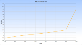
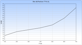 Rev 46 Poshan 71% UL.png20.8 KB · Views: 193
 -
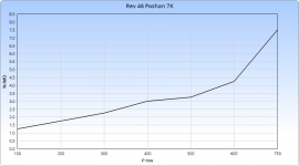 Rev 46 Poshan 7K 12BH7 triode.png20.4 KB · Views: 193
 -
 Rev 46 Poshan 7K 12AT7 triode.png18.9 KB · Views: 192
 -
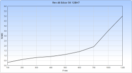 Rev 46 Edcor 5K 12BH7 triode.png19.6 KB · Views: 196
 -
 Rev 46 Edcor 5K 12AT7 triode.png20 KB · Views: 193
 -
Type 46 03_18_2017.zip2.7 KB · Views: 39
47 was developed as a pentode, but I didn't get very good results that way. More work is needed it seems. The schade graphs are running in pentode - it helped some, not as much I expected.
It makes a good triode, but not as good as 46.
It has very high gain, so I did not use a 12AT7 with it.
Win W5JAG
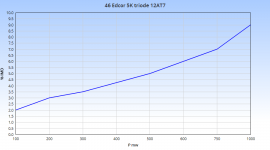
It makes a good triode, but not as good as 46.
It has very high gain, so I did not use a 12AT7 with it.
Win W5JAG
Attachments
-
Type 47 03_18_2017.zip2.8 KB · Views: 33
-
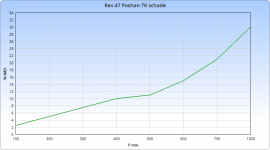 Rev 47 Poshan 7K schade.png19.7 KB · Views: 70
 -
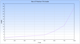 Rev 47 Poshan 7K triode.png18.6 KB · Views: 76
 -
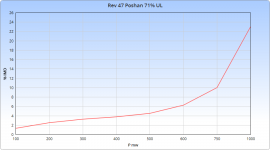 Rev 47 Poshan 71% UL.png19.2 KB · Views: 74
 -
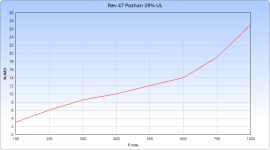 Rev 47 Poshan 29% UL.png19.3 KB · Views: 71
 -
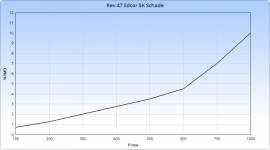 Rev 47 Edcor 5K Schade.png18.9 KB · Views: 75
 -
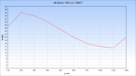
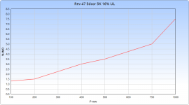 Rev 47K Edcor 5K 16% UL.png20.4 KB · Views: 85
 -
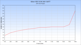
 Rev 47 Edcor 5K triode.png19.4 KB · Views: 80
Last edited:
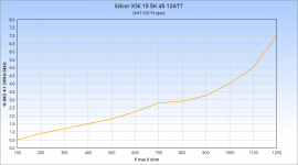
45 using the Edcor XSE15-5K.
test conditions:
unknown 45, branded Delco, FAA RCA 12AT7 blackplate, National Union 5W4GT
B+ 339
Vk 58
Rk 1500
Ik 39 ma
Pd 11
SMPTE IMD 4:1 200Hz:6kHz
SE amp cad predicts 3.1% 2nd harmonic distortion; 0.1% 3rd at 968 mw
Win W5JAG
test conditions:
unknown 45, branded Delco, FAA RCA 12AT7 blackplate, National Union 5W4GT
B+ 339
Vk 58
Rk 1500
Ik 39 ma
Pd 11
SMPTE IMD 4:1 200Hz:6kHz
SE amp cad predicts 3.1% 2nd harmonic distortion; 0.1% 3rd at 968 mw
Win W5JAG
Attachments
I don't see a practical way to eliminate the unresolved variable of the front end tube.
I've monkeyed around with the front end to try to make it work more consistently with the lower voltages for these tubes. That has included reducing the CCS current to about 6 ma. The amplification factor of the tubes is also different. 45 and 2A3 are similar, and less than 46, and all three are orders of magnitude less than 47 when it is run as a pentode. 12BH7 is less than 12AT7. So, the way things played out, on *this* DHT modified SSE board in its present state, it's clear that 46 and 47 work best with the lower gain 12BH7, and 45 and 2A3 need the higher gain 12AT7. Further tinkering could produce better results.
It's clear, even at this point of unrefinement, that the modified SSE board makes a very good simple DHT amplifier. Obviously better transformers produce better results as they always do, but a good DHT amplifier could be made for very little money with the modified SSE board and inexpensive transformers. It also seems clear that 46 and 47 make very good triodes on the modified SSE board, maybe better than 45 - but I don't have any way to do spectrum analysis. 45 could be better in that regard. It also seems clear that, as concerns the modified SSE board, that UL at the normal % impedances is unacceptable for 46, and no advantage for 47. Better UL transformers would move the overall distortion in each mode down, but I don't see better transformers changing the fundamental conclusion that 47 does not gain anything by using UL in single ended mode. Pentode is probably worth further exploring, but it will be less simple, maybe a lot less simple. 46 and 47 are spec'ed for a 7K load, and they tested a lot better at 7K than at 5K with the Poshan OPT, so with something like the Edcor at 7 or 8K, they may test better still. I didn't graph them with 5K on the Poshan OPT, but that data is in the attached file.
If I did not already have all the tubes to do this, and if I was the type of crazy person that was willing to roll the dice on cutting out the power tube sockets and risking total and irremediable destruction of the pcb, out of this lot I would probably choose 2A3 or 47 for purely practical reasons. 47 is cheap and abundant on eBay. Audiophiles have not discovered it, or turn their nose up at it. 2A3 is still in production, as are 12AT7 and 12BH7. 2A3 gives about 3 dB more headroom, so, if you need that, 2A3 is the way to go.
Note that I am not, and would never, advocate drilling out socket holes on a pcb and installing new sockets in their place, to make the board do something it was never intended by its designer to do.
Win W5JAG
Agreed. I would never butcher one of my boards to do these kinds of experiments even if I had the tubes and other components to do this which I don't.
Anyhow, W5JAG your posts in this thread make for interesting reading about the the kind of things that can be done with the SSE board.
307A / VT-225
Okay, I have 307A/VT-225 running on the DHT modified SSE board right now.
I didn't want an extra transformer on the bench, so I used the existing non ct 6.3 volt transformer that is running the front end, and built a virtual center tap to attach the 307A cathode resistor/bypass capacitor. I also have G3 attached to the virtual center tap.
It biased up right where I calculated and seems to be working as expected. is it permissible to use one filament transformer for evaluation purposes, or do I need to give the 307A it's own transformer?
The only curious result thus far is that 307A, like 47, does not seem to respond well to distributed load. I had it hooked up to the Poshan with the 5k lead to G2 for 71% impedance on G2, and this was marginally worse than full triode.
I'm running it at the max data sheet values - 300 volts; -30 on G1; 43 ma, but with a 7K load as a triode. Sounds clean and crisp. I briefly ran it up to about 25 watts, and it seemed fine there.
Win W5JAG
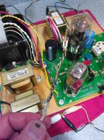
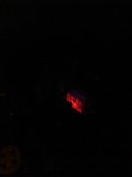
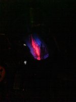
I swapped G3 from the cathode to the plate, and it lit up like Times Square in between the suppressor and the plate. Is this normal behavior for 307A, or is this a gassy tube?
I bumped up the voltage to see if it would burn off, and after an hour or so, the blue area diminished, but was still quite visible, and was still confined between the suppressor and the plate. I only have one 307A here at the house, the rest are at the warehouse of junk, so I don't have any others for comparison.
It seems to be working normally as far as I can tell. I do think it sounds better with G3 tied to the plate.
First pic is G3 tied to the cathode. Second pic is G3 tied to the plate.
Win W5JAG
Attachments
- Status
- This old topic is closed. If you want to reopen this topic, contact a moderator using the "Report Post" button.
- Home
- More Vendors...
- Tubelab
- Tubelab SE: Removing MOSFETs?