.... the idea of a very simple, very low cost, directly heated push pull amp, and I kind of think that this is one of the directions your thread will veer off into - a mosfet less simple quasi UL 46 SE, and a mosfet less simple PP quasi UL 46.
The obvious first use here of the phase splitter outputs / inputs is making an SSE board push pull. ...... Should be easy, really -
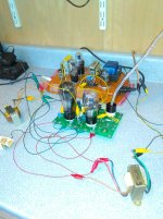
Yep, couple of minutes with clip leads is all it took to make the power amplifier stage work.
Front end ought to be pretty easy - one side is already an amp; I haven't looked at the board that close, but it would astonish me if there were not some way to haywire the other side into a phase splitter using the existing holes and traces.
Obviously, some refinement is needed - one side is 45, one side is 46. Might be pursued further. Might not.
Win W5JAG
Attachments
I found some 5930 here at the office, so I took one home last night to give it a try on the modified SSE board.
I'm not really a fan of 2A3, but the results on the modified SSE board looked pretty encouraging. I was running them in the range of 260 to 300 volts, unfortunately, this is in the range where 12AT7 seems to produce pretty variable results in the unmodified front end, so I used 12AU7 ( 6189, actually ) and 12BH7 as a substitute.
Preliminary results were encouraging. I didn't take any notes so this is from memory:
With a 5K Transcendar as the OPT, 12BH7, 1 Khz sine wave tone, and an 8 ohm resistive load, I saw 3.25 watts at the first indication of sine wave distortion. It took about 2.25 volts RMS input to a 12BH7 to get to there. 1 volt RMS gave about 4/10 of a watt.
Two tone IMD was pretty good, really. IIRC, with a 12BH7 it was about 7 or 8 % at 1 watt, about 3 or 4 % at one half watt, and at a quarter watt it fell below 1 %. The 6189 was a bit higher, but either would be acceptable.
I'm not really a big fan of 2A3 - just never cared much for the way they sound, but out of the DHT's that I am aware of, only 45 and 5930 are the short bottle types. This is important to me, because with these short tubes, a DHT modified SSE board would be a drop in replacement for the SSE board in the child resistant SSE. It would be a one or two evening project if I decided to go there.
Win W5AJG
This is really fascinating and I've been watching it closely.
So have I. Most people build amps by the numbers, and are happy with them. A few will go on to mod their amps to make them different or better, or whatever......then there are the few, the proud, the real hackers. Those who go where no tube has gone before.....not many of us.
Yes, I have cut up some boards to make something different, but I just made adapters to put the 307A's in my TSE (they work just fine on the 5 volt filament regulators). I never would have thought of drilling big holes for 5 pin sockets, but I might have to try it. I never would have put my SSE in the dishwasher either, but I had a really ugly one that had gone through at least two cap explosions........
making an SSE board push pull. I do recall at least one thread a few years ago on this.
I made one 6 or 8 years ago using an external phase splitter. In fact the driver board was an entire guitar preamp similar to that found in a Marshall amp. It drove an unmodified SSE board (except for some resistor values and a 12BH7 tube) to about 50 watts using a push pull OPT. I mentioned it somewhere and that prompted the push pull SSE thread.
http://www.diyaudio.com/forums/tubelab/171340-dual-simple-ses-push-pull-w-differential-input.html
I haven't looked at the board that close, but it would astonish me if there were not some way to haywire the other side into a phase splitter using the existing holes and traces.
There are two different paths to get there from here. I have done both years ago, and hacked up the board to get there quickly.
1) Split load PI. Leave one side of the 12AT7 as a gain stage CCS and all. Wire its plate directly to the grid of the other side of the 12AT7. Remove the CCS from the second side and replace it with a wire jumper. Swap out the 10 K in series with the CCS, and the cathode resistor for equal valued split load resistors (I used 33K I think). Remove the cathode bypass cap on that side. Sky wire the coupling cap for the now un fed output tube over to this cathode. Futz around with the bias (CCS current and cathode resistor) on the phase splitter side to get the plate voltage around 1/3 of B+.
2) An LTP design is possible, but more difficult due to the lack of a negative voltage source on the board. I don't remember the exact details. I jumpered the CCS chips in the 12AT7 plate circuits and used larger valued resistors in place of the 10K's. The grid resistors were not connected to ground, instead they were wired to the voltage divider that normally biases up the heater winding. A coupling cap is used for the input, and the unused input is connected to ground through a cap. The cathodes were connected together with both caps and one resistor removed. The remaining resistor was replaced with a larger resistor, or a CCS circuit.
I wonder if there is enough gain out of the 5842 to drive the 300B to clipping.
The 5842 can barely drive a 300B to clipping when driven by a good CD player or a line stage and being CCS loaded with a mosfet or tube buffer. Some users report not enough gain to hit clipping with a TSE driven by an iPOD or cell phone. Depending on your source a third stage may be needed with an unassisted 5842. I know many will find this unbelievable but a 12AX7 with a CCS load and a buffer will produce plenty of gain and remarkably low distortion. All 12AX7's are not created equal in this respect though. Some work better than others.
unfortunately, this is in the range where 12AT7 seems to produce pretty variable results in the unmodified front end
I assume you know this, but when operating an SSE on low voltage place a jumper across the 10 K resistor in series with the CCS. That resistor drops roughly 100 volts, just to take the heat off the CCS chip, and help make the board more blow proof when poking around in a live amp with a probe or screwdriver.
I assume you know this, but when operating an SSE on low voltage place a jumper across the 10 K resistor in series with the CCS. That resistor drops roughly 100 volts, just to take the heat off the CCS chip, and help make the board more blow proof when poking around in a live amp with a probe or screwdriver.
Even when jumpers are in the place of those two resistors, like W5jag I've found when the voltage is below 300V and particularly as it approaches 250V the sound starts to deteriorate rapidly with the 12AT7 in place. Also like him I've found that substituting with a 12BH7 is a good fix for this.
Also like him I've found that substituting with a 12BH7 is a good fix for this.
The 12BH7 will lower the overall gain a bit, but if that's OK, it is a good choice. I have used it on occasion, usually for lowering the gain.
I have a 6V6GT based SSE in a box somewhere, haven't seen it since I moved though. I don't remember what driver tube was in it last. I went through a bunch of tubes in that amp including 6K6's, 6G6's and a bunch of others. I settled on triode wired grey glass RCA 6V6GT's for the outputs. B+ is 325 volts with the 10K resistors jumpered. OPT's are the $22 Edcor XSE 15-5K. Closest thing to the 45 TSE that I could make on a low budget.
.... Leave one side of the 12AT7 as a gain stage CCS and all. ...
Good to know, because I have been curious about this point since the SPP omits the CCS. I didn't know if that was for economy of space on the board, cost, incompatibility with the phase splitter, or some other reason.
..... There are two different paths to get there from here. I have done both years ago, and hacked up the board to get there quickly.
1) Split load PI. ....
2) An LTP design is possible, but more difficult ....
Maximum simple being the goal, I think #1 above is ideal. But, also
3) a) An interstage transformer - the triode wired as the amp could drive it, and the transformer could split the phase; or
b) both sides of the twin triode could be wired in parallel, and then drive the interstage transformer. A transformer could also make it easier to drive when using the low gain front end tubes.
c) split the phase before the twin triode, let each side drive its respective power tube - maybe a transistor type transformer could be used here? Not a lot of DC voltage to have to deal with. Planning on trying this with the little 3Q4 type mini DH pentode.
4) Here's a really crazy thought - I've got a bunch of 7360 that I figured I would use as balanced mixers, but I have a nagging idea in the back of my head that one might make a pretty good phase splitter, with the added bonus of low noise and gain ....
a 12AX7 with a CCS load and a buffer will produce plenty of gain and remarkably low distortion. All 12AX7's are not created equal in this respect though. Some work better than others.
This is a terrific tip / hint that has been floating out there for the entire thread. I've just not followed up on it because so far I have been able to accomodate the reduced gain of a 12AU7 or 12BH7, and the slightly increased distortion has not been that much of an issue, especially since it seems like I have tin ears.
I'm a little curious as to why so many ( but not all ) 12AT7 seem to flounder when B+ declines below 300 volts into the CCS, but I've not followed up on that, either, because 12AU7 and 12BH7 can pick up here, albeit with reduced gain. I do have the voltage dropping resistor out of circuit - I didn't even install it on the CR SSE, and, in the board shown in this thread there is a jumper on the back of the board, taking it out of circuit.
I actually spent a fair amount of time playing with the front end, and measuring what kind of voltage gain I could get out of it at various input voltages, and B + voltages, etc., and then later figured out that the data was suspect because I had managed to pick a 12AT7 that was at the extreme far end of the bell curve with respect to B+ voltage.
Win W5JAG
Last edited:
I have been curious about this point since the SPP omits the CCS.
It's a little harder to dial in the bias with a CCS, and it will need adjusting when swapping tubes, like the TSE. The SPP doesn't need the extra gain that the CCS provides since EL84's are a lot easier to drive than 6L6GC's or KT88's.
An interstage transformer
Good transformers are hard to find or expensive. I tend to avoid them unless necessary, but that would be the easiest option.
I've got a bunch of 7360
I have a few of those. I was saving them for some vacuum tube music synthesizer experiments, but have never fired them up to see what they do.
a 12AX7 with a CCS
SY talked about the success he was having with a CCS loaded 12AX7 so I tried some. Mine are all used military surplus tubes from the 50's, and they are all over the place, but some worked very well.
why so many ( but not all ) 12AT7 seem to flounder when B+ declines
The 12AT7 was originally designed for RF amp, oscillator and mixer duty. Linearity was never a major design criteria. Most of them however are pretty good when run right at, or slightly above their upper spec for voltage and dissipation. The distortion generated is mostly 2nd harmonic, which is partially cancelled in a 2 stage SE amp like the SSE, or adds some life to a P-P amp which has predominately 3rd harmonic distortion.
In a design like the SSE where the CCS tries to keep the plate current at 8 to 10 ma, the voltage at the grid starts to get pretty close to zero at lower plate voltages. Try lowering the CCS current if you want to run them below 200 volts.
Dual Simple SE's in Push Pull w Differential Input
Reread that thread, interesting stuff, especially regarding the power supply wiring options.
Feedback: Seems like that fellow opted to use UL, so not much discussion beyond that.
I have some NOS vintage "30 watt" 6.6K PP OPT's, so that should be sufficient for 6550, EL34, etc., in triode. They also have a 10% tertiary winding, and I originally got them for sweep tubes and 6146, even though 10% is not much for UL.
I suspect the tertiary winding was actually for cathode feedback, so they should be ideal for a PP SSE. One leg of the tap to each cathode, and then the cathode resistor and bypass would connect to the center tap? I don't like the idea of a shared cathode resistor between two tubes. On that 11BM8 PP amp, the shared cathode resistor seriously degrades the channel with the unmatched tubes.
I'm thinking partial cathode bias, partial fixed bias. Set the cathode bias to a fail safe point, and then use additional fixed bias to tweak each power tube to match current? Soldering iron not even warm, and it's starting to get less simple.
So, I'm thinking expedience might dictate final development of the DH SSE variant for 45 or 2A3W/5930 tubes, that I can drop into the child resistant SSE chassis, and under the existing cage, with a minimum of chassis rework. That would produce a suitable result in the quickest manner, and free up that SSE board to start PP experimenting.
Another option to free up that SSE board: yank the TSE board from its chassis, say goodbye to the 801's, restore it back to 45/5930 spec ( easily done ), slap it on the child resistant chassis, or go really crazy and rig it for something like 6L6 ....
Or I may just go back to working on that transceiver.
Holidays and a troublesome trial schedule may slow progress to a crawl until after the new year.
Win W5JAG
I have done cathode feedback using the speaker windings since I don't have any OPT's with the 3rd winding. In a P-P cathode biased amp, use a separate cathode resistor for each tube. Ground the CT of the feedback winding, then connect each cathode bypass cap between the tube's cathode and it's respective feedback winding. This is how the SSE board is set up, no modifications needed, just substitute your 3rd winding for the speaker feedback connections to the board.
By the time you finish the DZ kit I may have my transceiver design done......not really since I have just began working on it and I don't even have an antenna up yet.
My employment agreement with Motorola ended last year so I am going to design myself a killer ham radio, since I was a radio designer for 30+ years. Unlike some of my projects this one will not be a Simple SDR. It will be stuffed full of high tech, high performance stuff, and mostly SMD assembly. I have been collecting the necessary equipment for about two years and now have a lab that pretty much duplicates what I had on my bench at Motorola with one exception. At Motorola my stuff only went to 1 GHz. Here, 3 GHz.
Or I may just go back to working on that transceiver.
By the time you finish the DZ kit I may have my transceiver design done......not really since I have just began working on it and I don't even have an antenna up yet.
My employment agreement with Motorola ended last year so I am going to design myself a killer ham radio, since I was a radio designer for 30+ years. Unlike some of my projects this one will not be a Simple SDR. It will be stuffed full of high tech, high performance stuff, and mostly SMD assembly. I have been collecting the necessary equipment for about two years and now have a lab that pretty much duplicates what I had on my bench at Motorola with one exception. At Motorola my stuff only went to 1 GHz. Here, 3 GHz.
Sigh.
I don't know that I'll ever get the DZ done, especially considering that I still haven't started on it ....
I was real gung ho on it when Bryan first showed it at Dayton, and he handwrote a 10% discount coupon for me to purchase one when it was available .... which turned out to be two or three years later .... but I saved the coupon and and he did honor it.
But they had production problems and it was delivered in bits and pieces; I didn't want to build it in bits and pieces, so when the last bits came in ( the tx strip, and some other minor bits, I think ) almost a year, maybe more, later, I had sort of lost interest, was building a new office, expecting another child .... Maybe he will like to build kits.
Quite an ordeal I think to manufacture something as complex as that radio as a one or two guy startup, so not complaining - I knew all that on the front end.
But, on the good side, I have a configuration(s) that are no longer available, as I have both the blank full pc remote control kit, and the local front panel kit, and the whole smack of roofing and IF filters for every mode, and all of the bandpass filters. The only parts I don't have are the tuner and 100 watt PA. I may still buy the tuner, but I have external PA's or could easily build one.
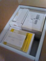
Here it is in a box where it is just sitting in the back room of my office .... along with an Elecraft K2 and all the options except the 100W PA, that I've had for so long .... one of the boxes is a revised main board ....
I like kits, I have several dozens of them, going way back, I'm just not very interested in building them. I think this is a combination of the attention span of a gnat, and a fundamental dislike of being told what to do - and with kits, following instructions is everything .... I'm better at things that can be broken up into small bits at a time.
I know SDR is the way of the future, but right now it leaves me kind of meh. I have an FT-950, which is pretty much all SDR, admittedly pretty low end, and it works fine with my modest antenna ( two element SteppIR on a roof tower ), but I'm just not that thrilled with it. I actually still prefer a KWM-2 with a 51S-1 as a side receiver.
Win W5JAG
I don't know that I'll ever get the DZ done, especially considering that I still haven't started on it ....
I was real gung ho on it when Bryan first showed it at Dayton, and he handwrote a 10% discount coupon for me to purchase one when it was available .... which turned out to be two or three years later .... but I saved the coupon and and he did honor it.
But they had production problems and it was delivered in bits and pieces; I didn't want to build it in bits and pieces, so when the last bits came in ( the tx strip, and some other minor bits, I think ) almost a year, maybe more, later, I had sort of lost interest, was building a new office, expecting another child .... Maybe he will like to build kits.
Quite an ordeal I think to manufacture something as complex as that radio as a one or two guy startup, so not complaining - I knew all that on the front end.
But, on the good side, I have a configuration(s) that are no longer available, as I have both the blank full pc remote control kit, and the local front panel kit, and the whole smack of roofing and IF filters for every mode, and all of the bandpass filters. The only parts I don't have are the tuner and 100 watt PA. I may still buy the tuner, but I have external PA's or could easily build one.
Here it is in a box where it is just sitting in the back room of my office .... along with an Elecraft K2 and all the options except the 100W PA, that I've had for so long .... one of the boxes is a revised main board ....
I like kits, I have several dozens of them, going way back, I'm just not very interested in building them. I think this is a combination of the attention span of a gnat, and a fundamental dislike of being told what to do - and with kits, following instructions is everything .... I'm better at things that can be broken up into small bits at a time.
I know SDR is the way of the future, but right now it leaves me kind of meh. I have an FT-950, which is pretty much all SDR, admittedly pretty low end, and it works fine with my modest antenna ( two element SteppIR on a roof tower ), but I'm just not that thrilled with it. I actually still prefer a KWM-2 with a 51S-1 as a side receiver.
Win W5JAG
Attachments
I first met Brian at the Orlando hamfest maybe 10 years ago. He had a dream, a mostly working prototype of what would become the Sienna and a few pages of what looked like a Heathkit manual. He had taken a buyout from Hewlett Packard after working on several of the RF signal generators of the day including the HP8656. I have two of them.
When he learned that I was a radio hardware engineer for Motorola we sat down and went over his design. There are many widely differing paths to design a two way radio, each with their own merits and pitfalls, and no two engineers will do things exactly the same way. His design was quite similar to what I would have done at that time given the constraints of making a 100% user buildable kit (limited or zero use of SMD).
I warned him of what turned out to be the worst parts shortage in recent history, especially for low volume parts. ROHS had killed many of them, and others just weren't being made because of limited production. I was working on a radio prototype at the time and parts would dry up before I could get the chain of command to sign off on a design, especially LDO's. I wished him luck, but secretly thought he would never succeed.
I would see him at the next TWO Dayton Hamfests with a working prototype and full manuals, but the worldwide parts shortage was keeping him from shipping anything. Obviously he did make it through all of that.....
The term SDR has been applied to a lot of things. Most of it low end or middle of the road radio equipment. None of this can ever be called a high performance transceiver since all or most of the filtering is in software. Take any of these to a high RF or high noise environment, and they will fall apart. All the digital filtering in the world is useless if the dynamic range of your converters is all used up and the desired signal is buried in the resulting noise floor. You absolutely have to have good band limiting and roofing filters ahead of the "S" part of the SDR if you want it to work on field day, contest day, or any day in the middle of a big city drowning in RF pollution.
If you haven't heard, the old Dayton hamfest is dead. The new one is no longer in Dayton......too soon to tell if it will survive. I will go next year, after that? Orlando is now a 1000 mile ride. Don't know if I'll go this year, missed the last two. It looks like the mega hamfests are a dying breed.
When he learned that I was a radio hardware engineer for Motorola we sat down and went over his design. There are many widely differing paths to design a two way radio, each with their own merits and pitfalls, and no two engineers will do things exactly the same way. His design was quite similar to what I would have done at that time given the constraints of making a 100% user buildable kit (limited or zero use of SMD).
I warned him of what turned out to be the worst parts shortage in recent history, especially for low volume parts. ROHS had killed many of them, and others just weren't being made because of limited production. I was working on a radio prototype at the time and parts would dry up before I could get the chain of command to sign off on a design, especially LDO's. I wished him luck, but secretly thought he would never succeed.
I would see him at the next TWO Dayton Hamfests with a working prototype and full manuals, but the worldwide parts shortage was keeping him from shipping anything. Obviously he did make it through all of that.....
I know SDR is the way of the future, but right now it leaves me kind of meh.
The term SDR has been applied to a lot of things. Most of it low end or middle of the road radio equipment. None of this can ever be called a high performance transceiver since all or most of the filtering is in software. Take any of these to a high RF or high noise environment, and they will fall apart. All the digital filtering in the world is useless if the dynamic range of your converters is all used up and the desired signal is buried in the resulting noise floor. You absolutely have to have good band limiting and roofing filters ahead of the "S" part of the SDR if you want it to work on field day, contest day, or any day in the middle of a big city drowning in RF pollution.
If you haven't heard, the old Dayton hamfest is dead. The new one is no longer in Dayton......too soon to tell if it will survive. I will go next year, after that? Orlando is now a 1000 mile ride. Don't know if I'll go this year, missed the last two. It looks like the mega hamfests are a dying breed.
I saw that they were moving it to a venue farther south, I guess down around Middletown? I think if they can keep everything on one property like Hara had, they will probably be okay, and hopefully get a place a little bigger than Hara for the inside exhibits - they could get way too crowded.
I have a big Federal trial set first week of June, so don't know if I can get away. I think last time I went was 2010, maybe, and I never paid much attention to all the gripes about Hara. It was no Taj Mahal, but I've seen way worse than that place. I suppose it could have run down worse since I saw it last, and I heard they had some kind of sewer geyser in the flea market.
The real dilemma with places like that is that fixing it up will cost a fortune, but tearing it down will also cost a fair amount of money - especially if it has asbestos or other regulated materials in it ( and it probably does ), and tearing out all the concrete, etc., to get down to bare earth, is also real expensive. I've struggled with this with some of my properties as they wear out - rebuild or tear down? I've torn down some, and rebuilt some. My warehouse of junk I'm on the fence about it ....
I looked at my invoice and I ordered my DZ July 9, 2010, and the last box with the transmitter strip had a shipping label dated April 29, 2011, so really not that big a delay. I guess it took me from Dayton to July to find that discount Brian had written me two or three years earlier. I also vaguely recall having some e mail exchanges with him to the effect that I was in no hurry to get the radio, and if he had people barking at him about shipping delays, as I'm sure he did, that mine could wait.
I took a look at the kit this weekend, for the first time really, and I have to say it is pretty impressive. Just the logistics of managing the parts inventory, and bagging the parts for the individual boards, looks like a herculean task - that thing must have thousands of individual parts, fasteners, etc. Some of the boards are partially fitted with SMD's, all the cables are pre built with their connectors, it really looks impressive. I think the estimated build time was 40 hours, but, I dunno - lots and lots of parts. Wouldn't surprise me if it took 60 hours or more to build it.
I see that Brian has a revised version of the radio out now. Hopefully he has turned the corner and is starting to see some return on the R & D he has in it, which would have to be considerable.
Win W5JAG
Last edited:
The new venue is the fairgrounds in Xenia. No hotels near there, very limited indoor space, and no paved outdoor space. Orlando thrives in an old rundown fairgrounds of similar qualities, so maybe? Plenty of hotel space in Orlando though, cheap too.
The $h!t storm in Dayton happened in 2011. Some idiot pounded a tent stake through the asphalt and into a water main. The resulting high pressure leak forced its way up through the asphalt in several places breaking a sewer pipe on the way. There was literally a geyser of crap spewing a couple of feet in the air. There was crap flowing out of some of the toilets and urinals in one of the buildings. After smelling this for a couple of hours I packed up and drove back to Florida.
https://www.youtube.com/watch?v=fHKUFu-yz-E
The arena has gotten noticeably worse over the years, and last year there were crews running around jury rigging everything (especially plumbing and electric) to satisfy the Trotwood code enforcement officials. This was still going on when I left Thursday evening, and the code cops were still going over some of the electric when I got there Friday morning. One of the DARA guys told me then that there would be no more hamfests at Hara.....that was believed to be a rumor then.
As of about 3 or 4 years ago he still had a waiting list for the Sienna. At least he is selling them. I haven't been able to talk to him at recent shows, too big of a crow in the booth.
The $h!t storm in Dayton happened in 2011. Some idiot pounded a tent stake through the asphalt and into a water main. The resulting high pressure leak forced its way up through the asphalt in several places breaking a sewer pipe on the way. There was literally a geyser of crap spewing a couple of feet in the air. There was crap flowing out of some of the toilets and urinals in one of the buildings. After smelling this for a couple of hours I packed up and drove back to Florida.
https://www.youtube.com/watch?v=fHKUFu-yz-E
The arena has gotten noticeably worse over the years, and last year there were crews running around jury rigging everything (especially plumbing and electric) to satisfy the Trotwood code enforcement officials. This was still going on when I left Thursday evening, and the code cops were still going over some of the electric when I got there Friday morning. One of the DARA guys told me then that there would be no more hamfests at Hara.....that was believed to be a rumor then.
Hopefully he has turned the corner and is starting to see some return
As of about 3 or 4 years ago he still had a waiting list for the Sienna. At least he is selling them. I haven't been able to talk to him at recent shows, too big of a crow in the booth.
That video looked .... bad.
I went to the hamvention site and looked at the pics of the new site. Looks like a nice fairgrounds, looks dicey for something like Hamvention. I guess the big grassed area is for the flea market? Hope it doesn't rain - which it seems like it did about half the time. Didn't look like they will have a lot of indoor exhibit space and it probably won't be very pleasant without air conditioning in those ag exhibit barns. Wonder where people will park?
Surprised there is not a suitable facility in a place as densely populated as the Dayton area.
Win W5JAG
That video looked .... bad.
The reality of being there smelled worse!
Surprised there is not a suitable facility in a place as densely populated as the Dayton area.
The real problem with Hara and just about every other place nearby is the fire code regulations about maximum occupancy. The Hamvention sells over 20,000 tickets each year. Hara (and others) are not rated for that many people, so the DARA people had to apply for a temporary waiver of the occupancy ratings. Trotwood became more and more strict about what they demanded, requiring more permits, inspections, and temporary repairs, as the arena grew more and more run down. At least twice in recent memory the Hamvention opening has been delayed by the fire marshals.
There has been talk about moving the show as far away as Columbus for the last few years, but last year things got serious.
The real dilemma with places like that is that fixing it up will cost a fortune, but tearing it down will also cost a fair amount of money
Back when you last visited, the car dealerships across the street had closed down, the area itself had run down a bit, and the old golf course looked like it was dying. That's all changed. Both car dealerships have been rebuilt and are doing a good business, new housing has been built nearby, the golf course looks good.......but the ugly old arena still remains. I wouldn't be surprised if a shopping mall springs up on the property.
The SV-811-10 continues to be a difficult nut to crack on the SSE board.
I've played around with it a little bit more, but the results, while improving, are still disappointing. I've been trying to drive it with an interstage transformer. The best results so far have been with a lower gain tube in the front end, and a 5:1 ratio interstage, and a transcendar 3K OPT. I'm probably not using the transformer optimally - I left the front end as is, and drive the interstage from the coupling capacitor.
The interstage transformer is better suited to a push pull stage, I think, but it's the only one I have. It's a Merit driver transformer, and has multiple ratios from about 2.5 to 5:1.
The SV 811 models well enough at the voltages I'm using, but the real world is completely different.
Win W5JAG
...... the CCS tries to keep the plate current at 8 to 10 ma, the voltage at the grid starts to get pretty close to zero at lower plate voltages. Try lowering the CCS current if you want to run them below 200 volts.
This ^^^^^ is next up on the short term agenda to try.
What ever happened to the LED in place of a resistor, cathode bypass cap, fad? The voltages at the cathode of the 12AT7 look about right for a single LED solution. May try this, but on an amp that is a work in progress, not sure how useful the data might be.
I was thumbing through a 1937 ARRL Handbook last week. A few things caught my attention. One was a suggested load of 3K for 45's at a plate voltage of 180 volts. That may actually be on the 45 data sheets - been a while since I looked at one, but that is rather contrary to the accepted value of 5K for a 45.
Another interesting circuit was a modulator, using a 45 to drive an interstage transformer, feeding a pair of 46's in class B push pull. That's not all that interesting, although I hadn't really thought of using the board single ended to drive an outboard push pull pair ( sort of a QRP version of Tubelab's TSE driving 845's ? ). What WAS interesting was the voltage specified for the push pull 46's - 500 volts. I realize tubes were a lot more disposable in 1937, but, wow, 500 volts. edit: IIRC, the 46's were shown as triodes.
Win W5JAG
As an aside, I used the mule on a real speaker while I was troubleshooting the TSE 801. I installed some 6K6's, and was pleasantly surprised at the quality of the sound through one of the small Yamaha's in the shack. It had no trouble pushing the Yamaha around.
Last edited:
SV811-10
..... Maybe the zero bias transmit tubes could be persuaded to work here.
Interestingly, the datasheet for the SV572-160 shows some single ended A2 data. 60v p-p grid drive, 30 volts grid, and 750 volts plate, projects 40 watts output, at 5% THD, into a 5K load. At lower plate voltages, it just shows that you need more positive grid voltage.
The modified SSE board would need only a small adjustable positive bias supply to be good to go. It looks so easy, there must be a gotcha that I'm not seeing. OPT's could be problematic - looks like some bone crunching currents involved, especially at lowish plate voltages.
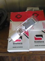
I actually fouind a pair of SV-572-160 here at the office, that I had forgotten about. I also have a bunch of SV-572B, and tubs of 572B / T-160L and 811A, which are all mu 160 AFAIK.
Win W5JAG
Attachments
Last edited:
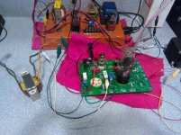
Here is the modified board with LED bias on the input tube.
An orange led set the cathode at at 1.97 volts. It does not get anywhere close to full brightness, not sure how important that is. The input tube is a 6189 (12AU7).
Power tube is a 45 set to 300 volts and 40 ma. Tubelab noted somewhere he has never seen a Pd for 45; I don't believe I have seen one, either. SE Amp Cad lists the maximum wattage for 45 as 8 watts, but I don't know where that came from. That seems low to me.
From a distortion standpoint, this works quite well. Two tone IMD does not exceed 1% up to 450 mw, from there it rises rather sharply, hitting 1.2% at 500 mw; 7% at 750 mw; and 13% at 1 watt. There is some trade off here, it can be made lower at the higher powers, but this increases the IMD somewhat at lower powers. OPT is a 5K Transcendar.
I don't think there is enough front end gain with this tube and this type of bias, so more work is needed, but it looks to be worth exploring. It certainly sounds good. When they designed the 45, they got it right.
Win W5JAG
Attachments
3K for 45's at a plate voltage of 180 volts. That may actually be on the 45 data sheets
It is.
Tubelab noted somewhere he has never seen a Pd for 45; I don't believe I have seen one, either.
I have 3 different data sheets for the 45, all printed by RCA at different times. They all list a maximum plate voltage of 275 volts and no plate dissipation spec.
I have since found a data sheet from Amalgamated Wireless Valve Co. PTY. Ltd. Sydney Australia dated OCT 1941. It calls the tubes "Radiotrons" which was an RCA trademark in the US. It lists the maximum plate voltage as 300 volts, and Pd max as 10 watts.
This data sheet also shows a set of operating conditions running the 45's quite hard into AB2 in push pull resulting in 19 watts of output. I tried this, and ran through my collection of well used old 45 tubes. While every one of my tubes is quite happy running 325 volts and 30 ma single ended in a TSE, only 3 or 4 could muster up the 100+ mA peaks needed to make nearly 20 watts. The wimpy tubes just ran out of filament emission and distorted badly. Even some of my old 2A3's (basically two 45's in parallel) couldn't cut it.
What ever happened to the LED in place of a resistor, cathode bypass cap, fad?
It works good, if you can find a suitable LED. You need your chosen voltage, and an LED with a low dynamic resistance the change in voltage drop as the current is cranked up. This is usually shown in the LED's data sheet, but modern high efficiency LEDs aren't as good as the old stuff, since this is not a design criteria.
Attachments
- Status
- This old topic is closed. If you want to reopen this topic, contact a moderator using the "Report Post" button.
- Home
- More Vendors...
- Tubelab
- Tubelab SE: Removing MOSFETs?