It is a bit tight in there.
I just had a few bits of walnut knocking around and had to make do with that.
The only components that are really near the bottom cover are the backs of a couple of the big electrolytics and every thing is well grounded but I think I will put some patches of thin clear polycarbonate under certain areas now that you have mentioned it. I don't want to block the ventilation either. I see that some people have cut the leads on the electrolytics and have lain them down flat.
The board is that near to the top plate because the sockets are soldered to it and that's where it ended up but it doesn't get very warm. Most of the heat seems to be above the plate, the tubes get hot but the transformers haven't so far.
Yes, Spendorite, that is where my speakers are. Our house is very small and there is nowhere else.
I had a pair of wall mounted JBLs but I blew them last year so I picked up those B&W floorstanders. I am amazed a t how the SSE drives them BTW; it has a really tight control of the bass and has plenty of volume. Not what I was expecting at all.
I need to change them for a pair of bookshelves but I don't want to lose the bass.
I do pull the speakers out to listen to them.
Actually, I spend my whole time pulling them out and angling them inwards and someone else spends their whole time putting them back in and straightening them up.
I ran my SSE for years and years and tens of thousands of hours with the pcb to chassis clearance as small as, or smaller, than depicted in this amp. I think my spacers were 1/4 or 3/8 inch. My chassis was only 1.5 inches in vertical height, so I had no choice but to keep it close. I had to lay the cathode bypasses flat just to make them fit.
Never a problem. Personally, I wouldn't worry about it.
Win W5JAG
Never a problem. Personally, I wouldn't worry about it.
Win W5JAG
I had a pair of wall mounted JBLs but I blew them last year so I picked up those B&W floorstanders. I am amazed a t how the SSE drives them BTW; it has a really tight control of the bass and has plenty of volume. Not what I was expecting at all.
I need to change them for a pair of bookshelves but I don't want to lose the bass.
Those B&W speakers probably have the same efficiency as mine. Mine are 88db efficient but present a tube friendly load.
With KT88 tubes in my SSE it gets loud enough fore me with the volume pot about the 10 o'clock position.
I recently completed my SSE but unlike you, mine's simply screwed down to a hunk of wood awaiting my finishing a case. Like you, I have been very impressed with the sound.
I don't own any floorstanding speakers to compare, and the music I tend to listen to isn't probably terribly bass heavy but I've been very pleased with the sound of my bookshelf speakers. They're Acoustic Energy AE1's and at least 20 years old. Probably not terribly efficient either but the SSE drives them easily.
I don't own any floorstanding speakers to compare, and the music I tend to listen to isn't probably terribly bass heavy but I've been very pleased with the sound of my bookshelf speakers. They're Acoustic Energy AE1's and at least 20 years old. Probably not terribly efficient either but the SSE drives them easily.
I am trying to help a friend on his SSE build. I built mine without the board point to point. I understand George added some protective components on the PS section to protect the rectifier tube. Does anyone know exactly what these parts are? I have read on the site before what they are but it can be a chore finding it again as I am sure others know.
Yes. The 2 diodes are 1N4007 and the inrush current limiter is CL-140.I am trying to help a friend on his SSE build. I built mine without the board point to point. I understand George added some protective components on the PS section to protect the rectifier tube. Does anyone know exactly what these parts are? I have read on the site before what they are but it can be a chore finding it again as I am sure others know.
Sent from my SM-G930F using Tapatalk
How are these extra parts not shown on the schematic wired in the circuit?
The CL140 goes between the power transformers HV CT and ground.
One diode goes between each HV hot lead (usually red) and the 5AR4 plate with the arrow pointing toward the rectifier tube (in series with the tube, boosting it's PIV rating).
These parts can easily be added to a custom build, or an early PC board build. Simply add a diode to the end of each red wire, cover it with heat shrink, and insert the diode lead into the green connector on the PCB. You can add the CL140 to the CT (red yellow) wire, but do not add shrink wrap to the CL140. Shrink on the solder joint is OK. The CL140 works by self heating, and it does get quite warm. Confining the heat to the part, will make its delay time much shorter, and possibly melt the heat shrink.
Many thanks George. I had the CL-140 pegged right but not the diodes. In a sense we have SS rectification before we get to the tube rectifier. I had a CL-90 laying around along with the UF4007 diodes and installed them into my amp just to be safe. The guy I helped with his build using your board had a rectifier tube to short out by putting jumpers on the 3 part places on the board. He had a time trying to find why his amp would not work and we finally figured out some extra parts were added. I told him to just jumper them since mine was built that way and sure enough it came to life. He is now enjoying the SSE amp immensely with his Jubilee Klipsch speakers and has installed the extra safety parts. I recommended the build to him so I was obligated to help him to get it to working properly. The CL-90 I used has more resistance when cold but I think it should work out well enough. I heated it with a hair dryer before installing and the resistance dropped to 17 ohms which should not have too much effect on the B+.
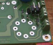
qwI don't know which pin numbers are which and I'm not in a position to check them at the moment but here's a shot of the pcb.
Sent from my SM-G930F using Tapatalk
- Status
- This old topic is closed. If you want to reopen this topic, contact a moderator using the "Report Post" button.
- Home
- More Vendors...
- Tubelab
- SSE up and running. Some questions.