Hi all,
I have just go my SSE up and running on the bench and it sounds absolutely great.
Thanks to all here and George for the help, I am just over the moon at the moment..

I had couple of issues in getting it running:
I followed Ty Bowers checkout procedure without the tube in and all the resistances checked out perfectly but when I went to measure the voltages I found the the fuse was popping as soon as I plugged in the power transformer.
After checking over the board and seeing nothing wrong and disconnecting filament wires etc., I decided to pull out the hexfreds and sure enough, that sorted it out.
One of them was reading a short in both directions and the other seemed to be reading a 0.3v drop in both directions.
I did not have the SS rectification switch or jumper wired and I had no rectifier tube in so they weren't really being used
So what did I do to blow them?
Could I have heated them up too much when I soldered them or can static blow them ( they do come in an anti-static bag)?
The voltages are:
Line voltage 243vac
B+ 442 vdc
Traffo 388 vac
12at7 filament 6.8vac
12at7 plates 304,309 vdc
5ar4 filament 5.7vac
As you can see, the filament voltages are a bit high but I did it at work and the line voltage at the factory is high at 243vac
The line voltage at home is only 228vac so that should be just fine.
One thing that concerns me is that the 12AT7 flashes brightly for about half a second around the base of the tube when the transformer is plugged in and then after a few seconds you can see the heaters slowly glowing up at the top of the tube.
Is that the heaters or is something arcing over at the bottom? It doesn't happen at the top where you can see the filaments sticking out.
Is it the high voltage?
Do I need to get a CL-90?
(Another 20 euro delivery charge on a 2 euro part, I've had a few of those already!)
Thanks again for all your help.
George
I have just go my SSE up and running on the bench and it sounds absolutely great.
Thanks to all here and George for the help, I am just over the moon at the moment..
I had couple of issues in getting it running:
I followed Ty Bowers checkout procedure without the tube in and all the resistances checked out perfectly but when I went to measure the voltages I found the the fuse was popping as soon as I plugged in the power transformer.
After checking over the board and seeing nothing wrong and disconnecting filament wires etc., I decided to pull out the hexfreds and sure enough, that sorted it out.
One of them was reading a short in both directions and the other seemed to be reading a 0.3v drop in both directions.
I did not have the SS rectification switch or jumper wired and I had no rectifier tube in so they weren't really being used
So what did I do to blow them?
Could I have heated them up too much when I soldered them or can static blow them ( they do come in an anti-static bag)?
The voltages are:
Line voltage 243vac
B+ 442 vdc
Traffo 388 vac
12at7 filament 6.8vac
12at7 plates 304,309 vdc
5ar4 filament 5.7vac
As you can see, the filament voltages are a bit high but I did it at work and the line voltage at the factory is high at 243vac
The line voltage at home is only 228vac so that should be just fine.
One thing that concerns me is that the 12AT7 flashes brightly for about half a second around the base of the tube when the transformer is plugged in and then after a few seconds you can see the heaters slowly glowing up at the top of the tube.
Is that the heaters or is something arcing over at the bottom? It doesn't happen at the top where you can see the filaments sticking out.
Is it the high voltage?
Do I need to get a CL-90?
(Another 20 euro delivery charge on a 2 euro part, I've had a few of those already!)
Thanks again for all your help.
George
Congrats, George!
Those Hexfreds could have been blown by static or heat. I believe they're also sensitive to the voltage generated by EMF collapse from the power transformer if power is cycled quickly. You have them installed the right way around too, right? I've made sillier mistakes when building.
The 12AT7 flash worries me a bit. Is that at the socket or is this inside the tube envelope? Can you tell whether this is the heater wires? It may just be the current surge with cold heaters.
I would use some kind of thermistor. It does not have to be a CL90 if you have access to other NTC types.
The flash is normal start up for many vintage, European manufacture, small signal, dual triodes. Don't worry about it.
As for the diodes, who knows. Many have no trouble with them, others ( like myself ) have no end of trouble with them. When I want to use a solid state rectifier, I use the potted style that plugs into the rectifier tube socket. These are not fancy, but they are convenient and seem bulletproof.
Congrats on getting it going!
Win W5JAG
Last edited:
CL-90 should help the filaments as you have to think of tubes to being like light bulbs in that regard. The more cycles the lower the life. CL-90 should help bring the voltage up slower helping life I would think.
They are used (suitable size) on aircraft light for that reason as they are expensive to replace. I bet they would help with car headlights etc.
I put a dimmer switch on my bathroom light as an experiment about 14-15 years ago and it's that old!
The light sensor used on screw in bases to turn on lights at night will give the same affect as they slowly bring the voltage up as it gets darker on the ones I've seen.
The GZ34/5AR4 does help with the slow warm up for the rest of the tubes (not the filaments) , but there is a diode mod that I think George puts on his latest PCB's for that amp (last few years) which helps the rectifier tube last. Diodes are put in series to pins 4 & 6 ( be careful of polarity) of the tube.
I forgot to also say that flash can be normal as I've read on various forums like Win W5JAG says!
Yes congrats! a great amp!
Last edited:
Diode mod info is in this thread:
http://www.diyaudio.com/forums/tubelab/202180-sparking-rectifier-tubes.html#post4713637
http://www.diyaudio.com/forums/tubelab/202180-sparking-rectifier-tubes.html#post4713637
Attachments
Thanks all for the advice.
Yes, W5jag, they are Nos Sylvania 12at7 and if that is normal that's fine.
The tubes were cheap so I'm not really worried about them as long as they don't blow something else up (my house). They seemed to be working happily enough though.
What is the flash? Is it the heaters or is it across the tube?
Thanks for the comments Sodacose, I will get a Cl-90 the next time I am ordering something, it can only help to take some pressure off the other stuff.
I do have the CL-140 and the diodes in stalled because it was one of the newer boards that I got with that mod on them.
And thank you rmyauk for that link, I was wondering how they worked as well, as they seem to be just a SS rectifier that makes the tube redundant.
But George explains it in that thread.
I can't do any more testing for now as I disassembled it pretty much straight away.
I need to get it into a chassis now, I routed the top plate today out of aluminium.
Bit of a chore.
Next time, I'm going to buy a chassis!
A yellow flash at the base of some tubes is normal. It's the exposed part of the heater element below the cathode heating up more quickly than the rest of the heater stuffed inside the cathode. Once the rest of the heater comes up to temp, the resistance across it equalizes and it glows more evenly.
Flash on the 12at7 may be normal depending on the brand of tube, google "mullard flash"
Ha ha! Yes that's it. There's a Youtube video of them doing exactly that.
I just checked the hexfreds they are the 12A version of the IXYS DSEI-12 which is the 1200V 11A version.
I wired it up to a lead and then plugged the lead in.
Probably not the cleanest way to turn something on.
A question please about connecting up speakers that are already connected to another amp.
It is very difficult to get behind my gear to connect and disconnect the speakers so I have connected my SSE to my main speakers which are already connected to the main amp in the room which is a Nad C370.
The SSE seems to be working fine with the Nad switched off.
Will everything continue to be fine with the SSE playing as long as the Nad is switched off?
Would it be ok to play the Nad with the SSE switched off?
I imagine that the transformers would generate a high voltage in their primaries from the voltage coming out of the Nad.
Is this correct?
Would it do harm?
Thanks,
George
Last edited:
Thanks guys for the replies.
Yes it is kind of dangerous to rely on remembering to turn off one amp to use the other.
I noticed that the SSE was very quiet the other day and then realized that the other amp was on as well. . I am also afraid of leaving it disconnected from the speakers because someone will turn it on with no load on it.
I have decided to do this headphone mod that Ty Bower outlined in this post (with a switch on it):
It will solve a number problems for me, it will give me a way of isolating the SSE from the speakers and the rest of the system while also putting a dummy load on the SSE if someone turns it on while it is disconnected. Of course it will also allow me to listen to it a lot more (there is a bit of a power struggle going on in the living room at the moment).
Today there was no music and I discovered that my 12at7 had blown (or something).
I noticed that the silver paint from the top of the tube was all gone so I checked the voltages again and everything seem ok.
9.3 milliamps going through the new tube and it seem that one of the filaments is broken.
Can these break like a light bulb filament from handling them?
Anyway, I have ordered 2 cheap GE 6201 RAF grade tubes for backup.
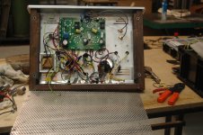
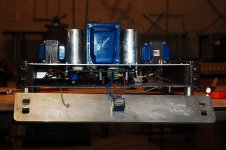
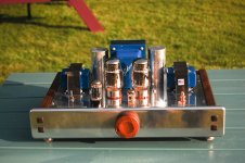
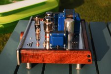
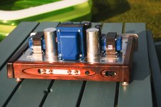
I think I am just about as finished I will ever be with it for the moment, I grounded all the metal bits yesterday.
Here are some photos. I learned that it is a lot more difficult to wire something into a chassis than on a bench. The wiring is a total mess, I was afraid to cut any of the transformer wires for the moment and I think I just twisted any wires that I thought would have AC in them together.
But there is no hum off it and it sounds great. there are only 66 milliamps running through the tubes so I'm wondering if I should lower the cathode resistor value and what that would do for me.That current seems low compared to the ones listed on the tubes and applications page for a Rk of 560, B+ of 412 (after the choke) and speaker dc resistance of 4 ohms (on an 8 ohm tap).
Is that how I measure it or do I need a dummy load?
Would it sound different with more dissipation?
Thanks to all,
George
Yes it is kind of dangerous to rely on remembering to turn off one amp to use the other.
I noticed that the SSE was very quiet the other day and then realized that the other amp was on as well. . I am also afraid of leaving it disconnected from the speakers because someone will turn it on with no load on it.
I have decided to do this headphone mod that Ty Bower outlined in this post (with a switch on it):
What did you use for your output transformers? I'll assume you've got an 8 ohm secondary on them.
I'd connect an 8 ohm, 10~20 watt non-inductive cemented wirewound resistor across the OPT secondary (basically, a dummy load where the speaker would normally go). Then I'd take a 120 ohm resistor (1/2 watt will probably be fine) and wire it in series with your headphone. Put the series connected 120 ohm / headphone combo in parallel with the 8 ohm dummy load.
It'll properly load the output transformer, and keep most of the power through the dummy load so it doesn't blow your headphones (or your eardrums).
It will solve a number problems for me, it will give me a way of isolating the SSE from the speakers and the rest of the system while also putting a dummy load on the SSE if someone turns it on while it is disconnected. Of course it will also allow me to listen to it a lot more (there is a bit of a power struggle going on in the living room at the moment).
Today there was no music and I discovered that my 12at7 had blown (or something).
I noticed that the silver paint from the top of the tube was all gone so I checked the voltages again and everything seem ok.
9.3 milliamps going through the new tube and it seem that one of the filaments is broken.
Can these break like a light bulb filament from handling them?
Anyway, I have ordered 2 cheap GE 6201 RAF grade tubes for backup.
I think I am just about as finished I will ever be with it for the moment, I grounded all the metal bits yesterday.
Here are some photos. I learned that it is a lot more difficult to wire something into a chassis than on a bench. The wiring is a total mess, I was afraid to cut any of the transformer wires for the moment and I think I just twisted any wires that I thought would have AC in them together.
But there is no hum off it and it sounds great. there are only 66 milliamps running through the tubes so I'm wondering if I should lower the cathode resistor value and what that would do for me.That current seems low compared to the ones listed on the tubes and applications page for a Rk of 560, B+ of 412 (after the choke) and speaker dc resistance of 4 ohms (on an 8 ohm tap).
Is that how I measure it or do I need a dummy load?
Would it sound different with more dissipation?
Thanks to all,
George
Attachments
Your amp looks terrific.
The tube lost it's vacuum - normally they are rugged devices and rough handling won't affect them. The GE 6201 is a fine tube.
66 mils sounds low to me. Current is cathode voltage divided by cathode resistance. Power is plate voltage minus cathode voltage, multiplied by cathode current.
You might want to try 470 to 430 ohms, maybe 390.
Win W5JAG
Sounds like a bad idea!
Looks like it would screw with the impedance or capacitance load that your amps are
seeing.
Regards
QUOTE=gcom;4732095]A question please about connecting up speakers that are already connected to another amp.
It is very difficult to get behind my gear to connect and disconnect the speakers so I have connected my SSE to my main speakers which are already connected to the main amp in the room which is a Nad C370.
The SSE seems to be working fine with the Nad switched off.
Will everything continue to be fine with the SSE playing as long as the Nad is switched off?
Would it be ok to play the Nad with the SSE switched off?
I imagine that the transformers would generate a high voltage in their primaries from the voltage coming out of the Nad.
Is this correct?
Would it do harm?
Thanks,
George[/QUOTE]
Last edited:
Yes, agreed.Sounds like a bad idea!
Looks like it would screw with the impedance or capacitance load that your amps are
seeing.
Regards
Not one of my better ideas.
I'll have to come up with something else.
Your amp looks terrific.
The tube lost it's vacuum - normally they are rugged devices and rough handling won't affect them. The GE 6201 is a fine tube.
66 mils sounds low to me. Current is cathode voltage divided by cathode resistance. Power is plate voltage minus cathode voltage, multiplied by cathode current.
You might want to try 470 to 430 ohms, maybe 390.
Win W5JAG
Thanks, W5JAG,
I got 37.3 volts dc across the 560 ohm cathode resistors and 412 volts dc between the plate and ground.
That gives me 66.4 mils current and a power dissipation of 24.9 watts.
Is this correct?
I better check my figures again.
Does the load on the OPTs affect this?
George
Plate voltage. 412v
Minus 37v cathode voltage,
= 374v divided by 560r = 0.6691 x 374 = 24.977 watts a bit much
If you are using EL34 max plate 25w. I would probably try 680r or 750r on those cathodes
Should put you at about 23 or 23.5 watts plate dissipation.
Regards
Minus 37v cathode voltage,
= 374v divided by 560r = 0.6691 x 374 = 24.977 watts a bit much
If you are using EL34 max plate 25w. I would probably try 680r or 750r on those cathodes
Should put you at about 23 or 23.5 watts plate dissipation.
Regards
Yes, agreed.
Not one of my better ideas.
I'll have to come up with something else.
Thanks, W5JAG,
I got 37.3 volts dc across the 560 ohm cathode resistors and 412 volts dc between the plate and ground.
That gives me 66.4 mils current and a power dissipation of 24.9 watts.
Is this correct?
I better check my figures again.
Does the load on the OPTs affect this?
George
Last edited:
I think I am just about as finished I will ever be with it for the moment, I grounded all the metal bits yesterday.
Here are some photos. I learned that it is a lot more difficult to wire something into a chassis than on a bench. The wiring is a total mess, I was afraid to cut any of the transformer wires for the moment and I think I just twisted any wires that I thought would have AC in them together.
But there is no hum off it and it sounds great.
Thanks to all,
George
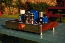
Very nice build and chassis layout.
Looks like there is hardly any space between the pcb components and the bottom metal cover.
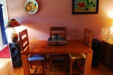
Is that where you normally have your speakers located ? With that large table and chairs between them
I imagine the stereo spacial effect will be compromised.
My wiring is a mess too but my SSE is dead silent.
I'll second the idea of increasing the distance between PCB and top plate. You can buy standoffs to drop the PCB somewhat. I also enlarge the holes for the tubes so that air circulates better from under the amp across the PCB and out by the tubes.
Even so, the top plate does warmup quite noticeably, but doesn't get hot.
Charlie
Even so, the top plate does warmup quite noticeably, but doesn't get hot.
Charlie
- Status
- This old topic is closed. If you want to reopen this topic, contact a moderator using the "Report Post" button.
- Home
- More Vendors...
- Tubelab
- SSE up and running. Some questions.