Hi all,
Five years since I was here building my SSE and it's been working great all this time, or so I thought. Could I pick your brains again please?
I've just been through and measured all the voltages throughout the powered circuit for the first time, so I could get my head around it all again in time for a couple of upgrades. For all I know it's been like this for five years...
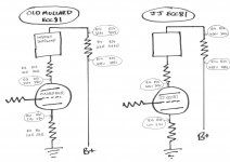
All is well apart from the circuit powering the preamp tube. I have two tubes, an old Mullard and a JJ, so I took the measurements with each in place and have drawn them out below. I didn't include all the components to hopefully make it clearer.
Looks like both tubes are being driven way too hard. I seem to be putting 404V on one side of the poor JJ!
Just to note all voltages were measured with the circuit powered but the resistances, although actual DMM readings, were done with the amp off.
It's weird because it seems to work and sound fine!
Thanks,
Mark
Five years since I was here building my SSE and it's been working great all this time, or so I thought. Could I pick your brains again please?
I've just been through and measured all the voltages throughout the powered circuit for the first time, so I could get my head around it all again in time for a couple of upgrades. For all I know it's been like this for five years...
All is well apart from the circuit powering the preamp tube. I have two tubes, an old Mullard and a JJ, so I took the measurements with each in place and have drawn them out below. I didn't include all the components to hopefully make it clearer.
Looks like both tubes are being driven way too hard. I seem to be putting 404V on one side of the poor JJ!
Just to note all voltages were measured with the circuit powered but the resistances, although actual DMM readings, were done with the amp off.
It's weird because it seems to work and sound fine!
Thanks,
Mark
Attachments
Looks like both tubes are being driven way too hard. I seem to be putting 404V on one side of the poor JJ!
It's weird because it seems to work and sound fine!
It won't be fine for long, since the plate voltage is 100V over max, and Pd is a watt over max.
It won't be fine for long, since the plate voltage is 100V over max, and Pd is a watt over max.
Unless something in the circuit has suddenly changed recently, it has been like this for the five years since I built the thing, and still works and sounds like it always has done. Today was the first time since initial birth power-up that I've probed the circuit with a voltmeter.
I can't make sense of it.
Unless something in the circuit has suddenly changed recently, it has been like this for the five years since I built the thing.
What's the transformer secondary voltage rating? Can you post the complete schematic, including the supply?
Last edited:
Nothing in the circuitry you've posted is going to increase B+. You need to be looking at the power supply... mains trx tappings ?
I don't think there is anything wrong with the B+. The same 450v is put across the output stage and all the voltages there are fine.
I think there is something wrong with the primary stage circuit as posted in OP diagram. For some reason the 450v B+ isn't dropping enough and by the time it ends up at the plate(s) of the 12AT7 it is way over spec. (I don't know what the plate voltage is supposed to be but looking at the data sheets for the tube 250v seems to be rated max at the plate)
Balls.....wish I'd left the voltmeter in the toolbox!
Mark
What's the transformer secondary voltage rating? Can you post the complete schematic, including the supply?
I don't know but I'm using bog standard GXSE15-8-5k OPTs. PT is the Hammond 374BX. Circuit is completely stock, with no CFB or UL.
Thanks! Maybe it will make more sense if I leave it alone for a couple of days and go back with a fresh pair of eyes - works when trying to fix old cars!
Mark
PT is the Hammond 374BX.
Ok, that's a 750VCT secondary. You also have a multi-tapped dual primary.
How is the primary connected, on the 120, 110, or 100V tap? If you're using the 110V or 100V tap,
move up one tap higher in voltage. That will reduce all the voltages by about 10%.
Ok, that's a 750VCT secondary. You also have a multi-tapped dual primary.
How is the primary connected, on the 120, 110, or 100V tap? If you're using the 110V or 100V tap,
move up one tap higher in voltage. That will reduce all the voltages by about 10%.
I don't know that either, but I'll check it out. So, reducing the whole B+ is what you're suggesting?
To my untrained eyes there is something more amiss than a slightly high B+ if I'm putting 400v on the plate of (JJ) ECC81/12AT7 which seems to have a max rated plate voltage of 250v.
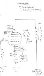
Can I post the circuit measurements for the output stage? These (below) show to me that the output (EL34) can handle the 450V B+...Apologies for the crap scan, shaded/grey numbers are for the other channel, both are effectively the same tho.
Marko
Attachments
reducing the whole B+ is what you're suggesting? To my untrained eyes there is something more amiss than a slightly high B+ if I'm putting 400v
on the plate of (JJ) ECC81/12AT7 which seems to have a max rated plate voltage of 250v.
Yes, that's right. It appears that you're not doing anything wrong, and the output stage does use the same supply voltage as the input stage.
I couldn't find what voltage Tubelab specifies for this amp, but maybe you can email them.
The SSE uses a CCS on the driver stage. It is supposed to be setup for 10mA of current. The CCS will adjust the plate voltage in order to maintain this current, so it doesn't really matter if the B+ is a little high. From your measurements across the 10k resistor, it looks like you are pushing more like 13mA, which is a little high. I also see that you have substituted the 10M45S for another part. You should adjust R13/23 to bring the current down to 10mA.
So why is your plate voltage so high? I suspect that your driver's tubes are getting weak. The CCS will keep raising the plate voltage to compensate for dropping tube emissions. I suspect that if you had measured the driver tube plate voltages after you built it, they would have been more in line.
The SSE runs these tubes pretty hard as it is, so running them even harder is not going to help tube longevity.
Sent from my XT1585 using Tapatalk
I think I'm getting to the bottom of the problem. I never did a checkout of the electrical parameters when I finished the build five years ago - I was just so relieved it worked and didn't explode that I decided not to push my luck.
Anyway it seems I've been running the 12AT7 at 170% rated power output all this time. I plotted the operating point on the load lines and it's almost off the page! 13mA and 330V at the screen. Poor little thing.
I think the root of the problem is to do with the CCS. I'm in Europe and at the time it was impossible to get hold of the 10M45 and so a suggested alternative was the Supertex DN2540 which is what I have installed. It was all a bit vague as to what value resistor to use at R13/R23 - I ended up with 100 Ohms, which I think is what is setting the current too high.
I'm going to swap these resistors for 150 - 200 Ohms and see how we get on.
Anyway it seems I've been running the 12AT7 at 170% rated power output all this time
. I plotted the operating point on the load lines and it's almost off the page! 13mA and 330V at the screen. Poor little thing.I think the root of the problem is to do with the CCS. I'm in Europe and at the time it was impossible to get hold of the 10M45 and so a suggested alternative was the Supertex DN2540 which is what I have installed. It was all a bit vague as to what value resistor to use at R13/R23 - I ended up with 100 Ohms, which I think is what is setting the current too high.
I'm going to swap these resistors for 150 - 200 Ohms and see how we get on.
Thank you Russ, I think we cross posted there....
Sounds like I'm on the right track. It was interesting how the old old Mullard tube seems to faring much better than the new JJ under these harsh conditions. In fact I think the JJ has broken down, as one channel runs at 5mA and the other at 10mA.
Thanks again, learning slowly but surely!
Sounds like I'm on the right track. It was interesting how the old old Mullard tube seems to faring much better than the new JJ under these harsh conditions. In fact I think the JJ has broken down, as one channel runs at 5mA and the other at 10mA.
Thanks again, learning slowly but surely!
I managed to break one of the terminal connections of the signal input on the PCB so I'm waiting for a new one to arrive before I can test more.
Regarding the driver stage, am I right in saying that excessive voltage on the plate of the 12AT7, assuming everything else in the circuit checks out, is a good indication of a worn tube?
Regarding the driver stage, am I right in saying that excessive voltage on the plate of the 12AT7, assuming everything else in the circuit checks out, is a good indication of a worn tube?
So, reducing the whole B+ is what you're suggesting?
Leave the power supply alone......
I've been running the 12AT7 at 170% rated power.....I think the root of the problem is to do with the CCS.
I think that there are two problems. The CCS's are not right, and at least one of your 12AT7's is cooked.
Looking at the voltage readings in post #1 it appears that neither CCS is doing anything, both are saturated, the same voltage appears on the input and the output (within measurement accuracy). This means that you have been running the poor little tubes with 455 volts applied to the plates through a 10K resistor. The old Mullard is still drawing 13 mA and dissipating 4.2 watts. The JJ is toast. Both were probably drawing a lot more current a few years ago.
The CCS's need to be fixed first. The curves shown for the DN2540 are not accurate in the 10 mA region, but it looks like 100 ohms would give about 20 mA of current. I would try something in the 220 ohm range. You should be able to try this with the old Mullard tube, since it still draws over 10 mA. The CCS is working correctly when there is 80 to 100 volts across the 10K resistor (8 to 10 mA).
If I have any 2540's here, I will test one, but your batch will be somewhat different.
Thank you for your reply George.
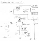
I soldered in the 220 Ohm R13/R23 this afternoon after a 40 mile round trip to find some. Looking at the circuit below I'd say you were bang on the money with that suggestion. The driver tube is the five year old abused Mullard. Looks OK from the figures would you say?
Interesting the 20 Volt discrepancy between both plates on the 12AT7...
Attachments
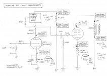
I was interested to see how a zero-time NOS Mullard driver would compare with the one I've been cooking for five years. The CCS seemed to have to put an extra 40V on the plates of the NOS driver to achieve the desired current, and there is still the 20V discrepancy between the two plates.
Thanks for your help gents.
Thanks for your help gents.
Attachments
- Status
- This old topic is closed. If you want to reopen this topic, contact a moderator using the "Report Post" button.
- Home
- More Vendors...
- Tubelab
- SSE odd pre-amp voltages