When a solution to a (perceived ) problem, presents a number of potential additional problems, it may not be the best solution to the problem.
When you have an engineer effectively re designing something that is not generally accepted to be flawed, I can't help but wonder if this train is starting to leave the tracks.
My two cents, FWIW.
Win W5JAG
Hear, Hear!
Build it first as the designer intended (which is a proven design), get it working then do whatever "improvements" you personally desire.
")
Your points are well taken. I've been trying to follow the experience of other builders, but I also don't have enough knowledge to contradict an electrical engineer when I'm at his workshop, so it's hard to know what call to make in a given situation.
I'm not doing anything about the MOSFETs until I really understand how these things work (1) in themselves and (2) in the TSE.
If Vgs cannot be exceeded, then the standard +/- 25v or 30v rating on common MOSFETs would not be suitable to the grid voltage of just about *any* output tube.
If that's true, then why wouldn't Vdss (drain-source voltage) be the key factor in the TSE application? If the gate begins conducting a channel across source and drain when the voltage across source and gate is about 4v, then the maximum drain-source voltage (900v in my present MOSFETs and 650v in the STMs) would seem to be more than enough.
In other words, if Vgs has a maximum limit of 30v, then why would it be possible to put 900v across source-drain?
Does the MOSFET function as a voltage multiplier?
Does the MOSFET function as a voltage multiplier?
It is used as a source follower. George describes it in more detail and the benefits over tradtional tube design on his site here:
Power Drive | Tubelab
He also has this page to let you calculate your own Power Drive based on your driver tube if you wanted to choose the optimum FET for your 300B (have your EE friend read this page):
Cookbook | Tubelab
Here is a tutorial on the fundamentals of a MOSFET source follower:
http://whites.sdsmt.edu/classes/ee320/notes/320Lecture36.pdf
Thanks! I've read the PowerDrive page several times but never saw the cook book. Have also been searching the web for basic MOSFET tutorials but never came across that one, which is *very* helpful.
Wish I could dive into this now but have to get back to work. Will work with all this tonight.
Wish I could dive into this now but have to get back to work. Will work with all this tonight.
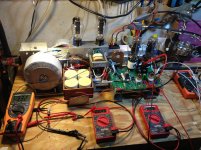
I'm about to install 25w chassis mount resistors at R6 and R7. When removing the old ones, the solder pads for R7 came off of the PCB on the top side. The bottom side for the one that meets R6 is peeling a little. Should I try to solder to that, or solder those legs of R6 and R7 directly, off board, since they touch anyway?
I made long legs for the R6 and R7 wires and soldered them together on the pad of R6. The other side of R7 was pretty toasted on the PCB, so I soldered that wire to the pristine F-JP pad the touches it. I haven't listened to it yet but the voltages check out.
I mentioned earlier that the 5842s used to have equal plate voltages when their trim pots were set to max, but at one point I started noticing a 10v difference that I had to equalize with the trim pots. When I re-did the checkout procedure today, I switched sides, and the 10v drop followed the tube from the right to the left channel. Hopefully I didn't damage one of the 5842s at some point.
R6 is now 10k 25w; R7 is now 6.8k 25w.
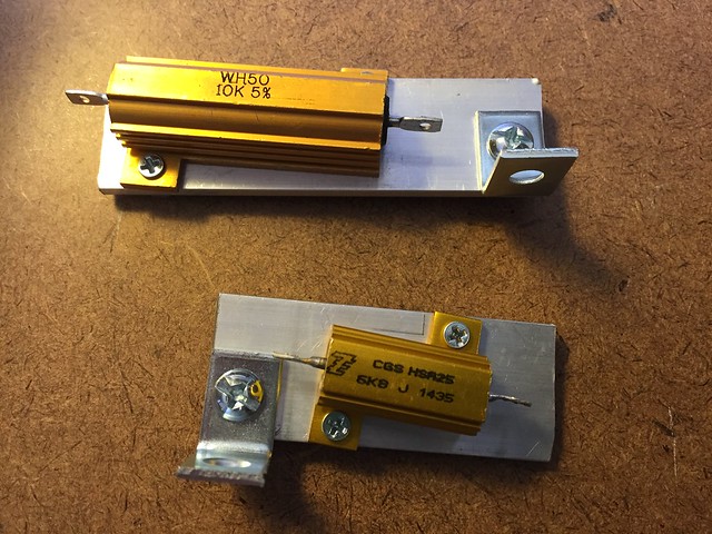 25w sinks by jeffdrouin, on Flickr
Here are the measurements from the end of today's procedure, with all tubes in and everything dialed in. I like the grid voltage and current bias numbers on the 300Bs.
B+ = 377 (measured across R30).
B- = -142
L bias (300B) = -60v; 91.5mA
R bias (300B) = -60v; 91.9mA
L plate (5842) = 162.5
R plate (5842) = 162.5
I wanted to measure the plate voltage on the 300Bs but had to quit and make dinner because my kids were going insane. Will try to measure it in the morning.
I mentioned earlier that the 5842s used to have equal plate voltages when their trim pots were set to max, but at one point I started noticing a 10v difference that I had to equalize with the trim pots. When I re-did the checkout procedure today, I switched sides, and the 10v drop followed the tube from the right to the left channel. Hopefully I didn't damage one of the 5842s at some point.
R6 is now 10k 25w; R7 is now 6.8k 25w.
25w sinks by jeffdrouin, on FlickrHere are the measurements from the end of today's procedure, with all tubes in and everything dialed in. I like the grid voltage and current bias numbers on the 300Bs.
B+ = 377 (measured across R30).
B- = -142
L bias (300B) = -60v; 91.5mA
R bias (300B) = -60v; 91.9mA
L plate (5842) = 162.5
R plate (5842) = 162.5
I wanted to measure the plate voltage on the 300Bs but had to quit and make dinner because my kids were going insane. Will try to measure it in the morning.
Last edited:
Are you sure you want 300B bias that high?L bias (300B) = -60v; 91.5mA
R bias (300B) = -60v; 91.9mA
On the Tubelab site, it says some 300B builders opt for a higher B+ and higher primary impedance on the OPTs in order to achieve 80-90mA of bias current and less distortion, for a more refined sound. That's what I was going for. My OPTs are 5k:80hm, 100mA, 15w.
The 300B datasheet I have for my tubes indicates "Maximum plate current for manually adjusted grid bias or self-biasing circuit: 100mA."
So, unless I'm misunderstanding something, I should be operating within but near the upper limits of the tube.
I measured the anode voltage of the 300Bs from pin 2 to ground at 334v ea. That seems to be a bit high, as the datasheet indicates 300v.
Here are the heatsinks I just made to add onto the existing ones at U1/D1 and the MOSFETs/10M45s. I cut up some leftover aluminum flat bar and glued them together with Arctic Alumina. I can't imagine these have a very effective thermal resistanc, but they're the best I can do for now. Hopefully they'll bring down the heat on those semis a bit.
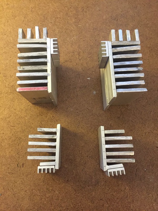 IMG_3123 by jeffdrouin, on Flickr
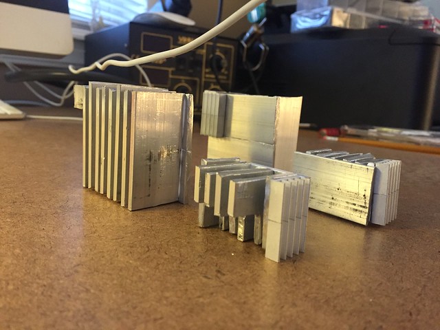 IMG_3127 by jeffdrouin, on Flickr
The 300B datasheet I have for my tubes indicates "Maximum plate current for manually adjusted grid bias or self-biasing circuit: 100mA."
So, unless I'm misunderstanding something, I should be operating within but near the upper limits of the tube.
I measured the anode voltage of the 300Bs from pin 2 to ground at 334v ea. That seems to be a bit high, as the datasheet indicates 300v.
Here are the heatsinks I just made to add onto the existing ones at U1/D1 and the MOSFETs/10M45s. I cut up some leftover aluminum flat bar and glued them together with Arctic Alumina. I can't imagine these have a very effective thermal resistanc, but they're the best I can do for now. Hopefully they'll bring down the heat on those semis a bit.
IMG_3123 by jeffdrouin, on Flickr
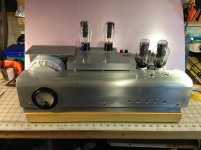
IMG_3127 by jeffdrouin, on FlickrEverything is dialed in after the changes we made, so I plugged it in and listened through my good speakers. MUCH improved. Full, clear sound, musical detail, excellent bandwidth, very quiet (quieter than my SS amp, actually), and much more volume than I was getting before.
I wouldn't mind a little more volume for rocking out, but playing directly from CD player with no preamp is perfectly adequate, and I'm happy with it. I have a 50k DACT attenuator that goes from 50k to 35k resistance. Maybe a 25k or 10k attenuator would give me significantly more volume?
Some component temperatures are still over 130*F, and I'll probably swap in different MOSFETs at some point, but I'm considering the project finished.
Now to find a good turntable and phono / line preamp projects to make this thing really sing!
I'll post more pics in the photo thread, but here it is:
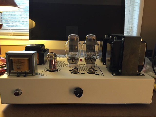 Tubelab SE 300B by jeffdrouin, on Flickr
Thank you again to everyone who dedicated time and attention to helping with this project! Couldn't have done this without you, and I really appreciate your patience with all my newbie mistakes and questions.
I wouldn't mind a little more volume for rocking out, but playing directly from CD player with no preamp is perfectly adequate, and I'm happy with it. I have a 50k DACT attenuator that goes from 50k to 35k resistance. Maybe a 25k or 10k attenuator would give me significantly more volume?
Some component temperatures are still over 130*F, and I'll probably swap in different MOSFETs at some point, but I'm considering the project finished.
Now to find a good turntable and phono / line preamp projects to make this thing really sing!
I'll post more pics in the photo thread, but here it is:
Tubelab SE 300B by jeffdrouin, on FlickrThank you again to everyone who dedicated time and attention to helping with this project! Couldn't have done this without you, and I really appreciate your patience with all my newbie mistakes and questions.
Last edited:
dealing with high voltage transformers
I learned a lot about this board/amp by following your build. Thank you for all your posts!
Your amp has turned out well!
If anyone has noted my as yet unfinished build with it's issues I can advise that the psu needs to be built from a tx of no more than 300-0-300 in order to use the built in bias system without alterations. I've opted to use a separate tx for the bias system in order to keep my high voltage transformer and its accompanying low ripple, fast recovery psu.
Things are looking good with only a heater voltage to tame (I've got over 7 volts on the 5842 heaters). I'll be running my 300Bs at 400VDC for B+ and 60mA - a reputed sweet spot for harmonic supression. 8.3 W output, dissapating 24W. I just hope my EH300Bs are up to it!
Cheers!
Thanks! I'm glad you found it helpful. I kind of over-documented it in hopes that it would be useful to other people attempting the project. I'll be posting a final BOM and assessment once I can get a break in the next week or two.
So, if I understand correctly, you're using one power transformer to drive the B+ rail, input tubes, and output tubes, and another power transformer to drive the B- rail? How did you finagle that?
So, if I understand correctly, you're using one power transformer to drive the B+ rail, input tubes, and output tubes, and another power transformer to drive the B- rail? How did you finagle that?
Thanks for posting data!
It was indeed you extensive reporting that got me to figure I could not shed enough of the excessive voltage and by the by, in my case it shorted the Mosfets creating my strange numbers.
Adding another tx is just a matter of tapping the mains and sending the power to the board at T1-4 & T1-5 (the 400V B+ comes in at the positive lead of the missing C5 cap). I was careful with the phase and center tap but I'm not sure even that was necessary.
I have today to do some work on it; I hope to report soon
now we're talkin'
OK, It is up and running and full of surprises.
That B+ that was coming in at 428VDC unloaded only makes 330 when playing music. That's alright, just a bit off from what I had hoped for anyway: my target was 350. 428 had me worried.
I got 167V at max on the plates of the 5842 but a funny thing: the heaters for the 5842 show 5.5VDC and .3VAC according to my meter. Anyone else notice this kind of voltage?
I have the bias set to 52mA. It has held pretty steady in multiple trials. output tx is a 5k primary/8 Ohm secondary. I have been testing with nominal 6 Ohm speakers.
I have been monkeying with the capacitance of the PSU. I'm liking the full available levels for my clclc. First cap is 1uF (thus the need for high voltage tx). L is 1.5H/40 Ohm triad choke, then parallel 40uF PMK with a 0.25uF PIO bypass...and repeat! Why all the fuss using a 1uF input cap? It was the input cap that produces the fastest recovery for high level transients and kept ripple down to a minimum.
How does it sound? Pretty darn good! I'm comparing it to a Nelson Pass Aleph J that I use there in my soldering room. It is driven by a preamp that is just the front end of a NP BA-3 (very respectable but the input is a lowely Magnavox from Philips though it has been recapped and has that nifty TDA 1541 chip. Speakers are B&O redline 60's. This 300B has less power but sounds bigger! I'm still listening "into" the music and finding many pleasing details and tonal refinements. Drums are particularily "happening"
I will move it upstairs to the big room in time. Right now I have to say it's been a good learning experience and Big thanks to all contributors to it!
George Anderson, I hope you are doing great/better down in FL
Cheers!
OK, It is up and running and full of surprises.
That B+ that was coming in at 428VDC unloaded only makes 330 when playing music. That's alright, just a bit off from what I had hoped for anyway: my target was 350. 428 had me worried.
I got 167V at max on the plates of the 5842 but a funny thing: the heaters for the 5842 show 5.5VDC and .3VAC according to my meter. Anyone else notice this kind of voltage?
I have the bias set to 52mA. It has held pretty steady in multiple trials. output tx is a 5k primary/8 Ohm secondary. I have been testing with nominal 6 Ohm speakers.
I have been monkeying with the capacitance of the PSU. I'm liking the full available levels for my clclc. First cap is 1uF (thus the need for high voltage tx). L is 1.5H/40 Ohm triad choke, then parallel 40uF PMK with a 0.25uF PIO bypass...and repeat! Why all the fuss using a 1uF input cap? It was the input cap that produces the fastest recovery for high level transients and kept ripple down to a minimum.
How does it sound? Pretty darn good! I'm comparing it to a Nelson Pass Aleph J that I use there in my soldering room. It is driven by a preamp that is just the front end of a NP BA-3 (very respectable
but the input is a lowely Magnavox from Philips though it has been recapped and has that nifty TDA 1541 chip. Speakers are B&O redline 60's. This 300B has less power but sounds bigger! I'm still listening "into" the music and finding many pleasing details and tonal refinements. Drums are particularily "happening" I will move it upstairs to the big room in time. Right now I have to say it's been a good learning experience and Big thanks to all contributors to it!
George Anderson, I hope you are doing great/better down in FL
Cheers!
Attachments
Thanks guys for the complements!
I checked my meter used on the 5842 heaters, it is working properly so that mystery continues...
I had to do a bit of surgery due to a miscalculation on the height of the input tubes. Some new parts needed.
If anyone is interested, I'll compare the finished product w a purpose built 45 in my main system which features Klipsch La scalas. Ive always wondered if they gained anything more than power when they developed the 300A/B...
- Status
- This old topic is closed. If you want to reopen this topic, contact a moderator using the "Report Post" button.
- Home
- More Vendors...
- Tubelab
- Tubelab SE 300b Build Thread