I have some tubes with nice straight pins.
Those hold the tabs under the pins in good alignment for soldering.
That way I don't need as much force to insert and remove tubes.
Have you ever noticed how the pins and solder tabs wiggle around?
Once you solder them to the PCB then they cant move and if they are misaligned it can make tubes difficult to insert.
Last edited:
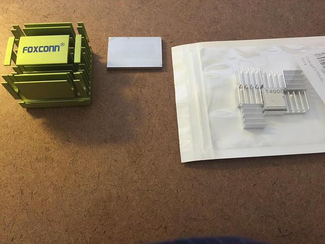
I opened an old Linux box and found a couple of heatsinks that might be useful. There's a 1/2" deep one with an embedded fan from the video card that could probably sit atop Q1/Q2 and U2/U3 and still allow room for the 300Bs to poke through the top plate. No idea what voltage the fan runs at but shouldn't be hard to figure out. Might be able to get the green one from the motherboard to attach to D1/D2.
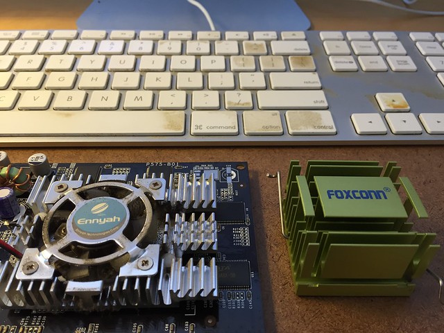 heat-sinks by jeffdrouin, on Flickr
Also found a couple of 3" case fans that might help to draw hot air out and keep a draft over the heatsinks. Would prefer to do this without fans, though, for the sake of quietness.
heat-sinks by jeffdrouin, on FlickrAlso found a couple of 3" case fans that might help to draw hot air out and keep a draft over the heatsinks. Would prefer to do this without fans, though, for the sake of quietness.
I have some tubes with nice straight pins.
Those hold the tabs under the pins in good alignment for soldering.
That way I don't need as much force to insert and remove tubes.
Have you ever noticed how the pins and solder tabs wiggle around?
Once you solder them to the PCB then they cant move and if they are misaligned it can make tubes difficult to insert.
I prefer to use tube sockets with the fork type pin retainers. They work well for me. When soldering them to the pcb,
like most people I try to get a nice rounded mound of solder around the socket pins with sufficient flow through to
the other side. Haven't had a problem so far. In fact I don't mind if the tube pins fit tightly because with the SSE I switch
power tubes a lot ( tube rolling you know
") ) so I want the sockets to last as long as possible.
) so I want the sockets to last as long as possible. Of course I see your point but I prefer not to take a chance and always solder the sockets to the board without the tubes in them.
A 12 volt fan running at reduced voltage will be relatively quiet and still move sufficient air in all likelihood. There is dc voltage at the input and output of the regulator that can be used to power the fan.
The fan on mine is a small 12 vdc device, and i power it from the dc at the regulator input.
Win W5JAG
The fan on mine is a small 12 vdc device, and i power it from the dc at the regulator input.
Win W5JAG
Yes. I and others have TSE without fan and without overheating problem. 300B tubes are microphonic, meaning that they are sensitive to vibration. Why add more potential problem to it?Would prefer to do this without fans, though, for the sake of quietness.

Put adequate size heatsink and be done with it.
I've been searching for heatsinks that will fit between the board and top plate of the amp, as well as mounting options. The easiest would be an adhesive, rather than bolting. Would this Arctic Silver adhesive work?
Manufacturer says it's good up to 150*C
Amazon.com: Arctic Silver Arctic Alumina 5g Premium Ceramic Thermal Cooling Adhesive Set (AATA-5G): Computers & Accessories
Manufacturer says it's good up to 150*C
Amazon.com: Arctic Silver Arctic Alumina 5g Premium Ceramic Thermal Cooling Adhesive Set (AATA-5G): Computers & Accessories
Heatsinks sticking out the top look OK to me. The ones I used were repurposed and ugly but I bet nicer looking one could be had.
If you have not soldered them yet work out the heatsinks for the four semis that are all together. It was hard to retrofit an extra sink after I trapped the screws when I soldered the parts.
If you have not soldered them yet work out the heatsinks for the four semis that are all together. It was hard to retrofit an extra sink after I trapped the screws when I soldered the parts.
Last edited:
Personally, I would go with harder but surer way of mounting heatsink.The easiest would be an adhesive, rather than bolting.
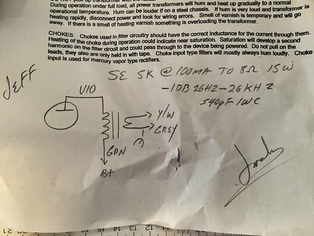
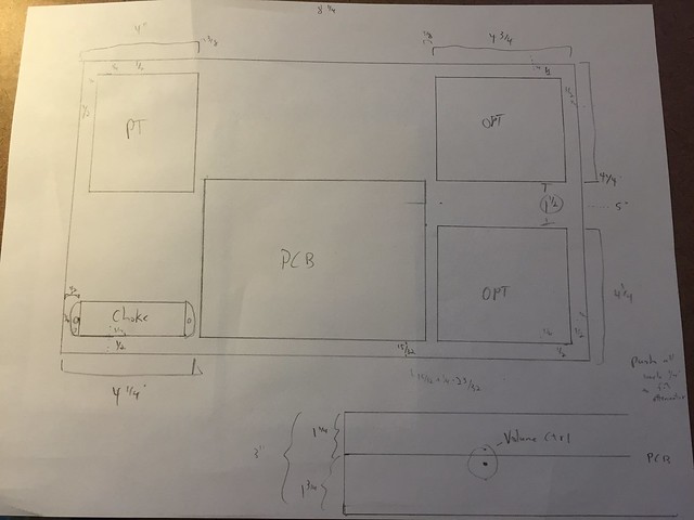
I've laid out the chassis and am getting ready to start drilling holes and mounting iron. I gather, from the schematic supplied by Electra-Print, that the violet and green wires are the OPT inputs, while the yellow and grey go to the speaker binding posts?
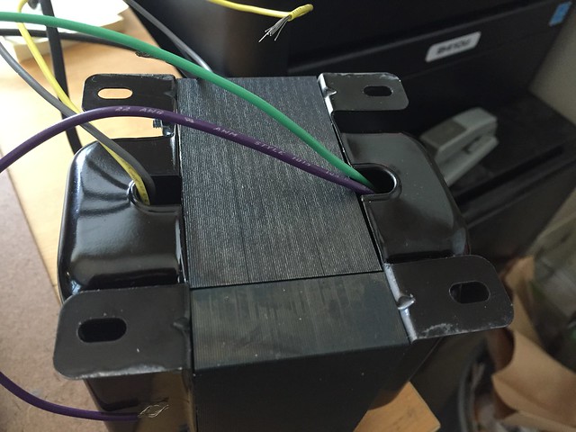 OPTs by jeffdrouin, on Flickr
 OPTs by jeffdrouin, on Flickr
OPTs by jeffdrouin, on Flickr
OPTs by jeffdrouin, on FlickrAlso, in addition to confirming that I've read the schematic correctly, would there be any potential problems mounting the power and output transformers 1/4" from the edges of the chassis?
The chassis is aluminum and there is a steel cage that covers it, so the PT and OPT bell covers would be 1/4" away from it. Not sure if that proximity might cause interference.
I imagine it's fine, but as I plan out all the little details I'm realizing there are so many things to consider.
The chassis is aluminum and there is a steel cage that covers it, so the PT and OPT bell covers would be 1/4" away from it. Not sure if that proximity might cause interference.
I imagine it's fine, but as I plan out all the little details I'm realizing there are so many things to consider.
Thanks, zman01. PT, OPTs, and choke are all on top of the chassis, in the corners, with the circuit board in the center. I ended up with a 17 x 10 x 3 aluminum chassis, with layout (A) as listed in this thread, because there was a Hammond cage available for it.
I agree 1/4" is tight but all of the wires and working bits will be oriented toward the more spacious sides, so I'm not too worried about it.
I agree 1/4" is tight but all of the wires and working bits will be oriented toward the more spacious sides, so I'm not too worried about it.
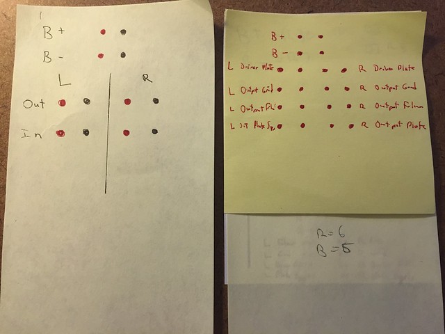
Same here, evanc. My plan is to drill access holes for the trim pots and also to place an array of chassis-mounted tip jacks for the test probes. That way I wouldn't need to take it apart to make adjustments. For the trim pot and OPT/Choke wire holes, I picked up a box of 180 assorted rubber grommets at Harbor Freight for like $6. I *love* that place.
These are some sketches of what the tip jack array might look like. To make it simple I could just have jacks for B+, B-, driver tube voltage, and output tube bias, since those are the most likely to get adjusted over time. On the other hand, if I'm going through the trouble to do that, then why not include jacks for all possible tests and be done with it?
There's room for it in the chassis, but I don't know if there would be a detrimental affect with all those wires leading off key places on the PCB.
 Chassis layout by jeffdrouin, on Flickr
I figure I should place the rows of tip jacks on the chassis top plate, under the cage, which would be safest option. They would be located behind the PCB between the PT and OPT in this drawing:
 Chassis layout by jeffdrouin, on Flickr
Or they could go on the back, which would be more convenient since I wouldn't have to take the cage off for access, and possibly a cooler location, which might be desirable since they are made of plastic with an 85*C maximum operating temperature. However, it would sure suck if someone were to stick something conductive into the jacks carrying the full B+ voltage.
For access, I'm also planning to cut a panel out of the chassis top plate over the PCB. The PCB will be mounted on bolts from the top plate, and will be situated about 1 1/4" below the top plate to allow room for the semiconductors and heatsinks. That depth will also allow the 300Bs plenty of room to fit under the cage and above the top plate. In the drawing below, you'll see a rectangle just inside of the PCB mount holes where I'm planning to cut the panel. I'll use big washers on the mount bolts for the panel to rest on.
 Chassis layout by jeffdrouin, on Flickr
In that situation, components on the board periphery wouldn't be completely uncovered when the panel is removed, but that might not be such a big deal. If I really had to get to something there I could always open the bottom and remove the board. However, since it also makes sense to provide complete access if I'm going through the trouble, I'm also thinking of cutting around the mount bolts to make the panel equally as wide or wider than the PCB. In that way, the mount bolts would be situated in tabs on the top plate. My concern there is that the tabs might be too weak to handle the pressure of inserting and removing tubes. I could remedy that by using 3-1/2" screws that are also secured to the bottom plate.
Also in the area of information overload, you'll see that I'm starting to plan vent holes around the tube sockets (3/8" dia. every 15*). Once those are set, I'll drill a pattern of holes (probably 1/4" with 1/8" space in between) over the PCB and heat sinks, with a similar pattern in the bottom plate, to allow for hot air to escape.
I am concerned about the semiconductors overheating. I've got a 1-5/8" x 1-5/8" x 1-1/4" aluminum heatsink from a computer motherboard (the green one) that I can attach to the basic sink for D1/U1 with a shim I cut from 1/8" aluminum flat bar. I also ordered this 76mm x 43mm x 22mm one from Amazon that will arrive in a couple days. Not sure which would be better.
 Heatsinks by jeffdrouin, on Flickr
The small silver ones are for Q1/Q2 U2/U3 cluster. All heatsinks will be attached with permanent thermal adhesive.
If you have thoughts about any of this, they'd be much appreciated!
These are some sketches of what the tip jack array might look like. To make it simple I could just have jacks for B+, B-, driver tube voltage, and output tube bias, since those are the most likely to get adjusted over time. On the other hand, if I'm going through the trouble to do that, then why not include jacks for all possible tests and be done with it?
There's room for it in the chassis, but I don't know if there would be a detrimental affect with all those wires leading off key places on the PCB.
Chassis layout by jeffdrouin, on FlickrI figure I should place the rows of tip jacks on the chassis top plate, under the cage, which would be safest option. They would be located behind the PCB between the PT and OPT in this drawing:
Chassis layout by jeffdrouin, on FlickrOr they could go on the back, which would be more convenient since I wouldn't have to take the cage off for access, and possibly a cooler location, which might be desirable since they are made of plastic with an 85*C maximum operating temperature. However, it would sure suck if someone were to stick something conductive into the jacks carrying the full B+ voltage.
For access, I'm also planning to cut a panel out of the chassis top plate over the PCB. The PCB will be mounted on bolts from the top plate, and will be situated about 1 1/4" below the top plate to allow room for the semiconductors and heatsinks. That depth will also allow the 300Bs plenty of room to fit under the cage and above the top plate. In the drawing below, you'll see a rectangle just inside of the PCB mount holes where I'm planning to cut the panel. I'll use big washers on the mount bolts for the panel to rest on.
Chassis layout by jeffdrouin, on FlickrIn that situation, components on the board periphery wouldn't be completely uncovered when the panel is removed, but that might not be such a big deal. If I really had to get to something there I could always open the bottom and remove the board. However, since it also makes sense to provide complete access if I'm going through the trouble, I'm also thinking of cutting around the mount bolts to make the panel equally as wide or wider than the PCB. In that way, the mount bolts would be situated in tabs on the top plate. My concern there is that the tabs might be too weak to handle the pressure of inserting and removing tubes. I could remedy that by using 3-1/2" screws that are also secured to the bottom plate.
Also in the area of information overload, you'll see that I'm starting to plan vent holes around the tube sockets (3/8" dia. every 15*). Once those are set, I'll drill a pattern of holes (probably 1/4" with 1/8" space in between) over the PCB and heat sinks, with a similar pattern in the bottom plate, to allow for hot air to escape.
I am concerned about the semiconductors overheating. I've got a 1-5/8" x 1-5/8" x 1-1/4" aluminum heatsink from a computer motherboard (the green one) that I can attach to the basic sink for D1/U1 with a shim I cut from 1/8" aluminum flat bar. I also ordered this 76mm x 43mm x 22mm one from Amazon that will arrive in a couple days. Not sure which would be better.
Heatsinks by jeffdrouin, on FlickrThe small silver ones are for Q1/Q2 U2/U3 cluster. All heatsinks will be attached with permanent thermal adhesive.
If you have thoughts about any of this, they'd be much appreciated!
Last edited:
You can see that my SSE uses the whole 12 x 10 chassis, and the cage fits so tight, I have to angle it on. As long as you can get the cage on, and it doesn't short anything, it'll be fine.
Question: If you are using a cage, why bother putting the board under the chassis? Seems like a lot of extra work for no benefit, and several disadvantages such as heat dissipation and voltage adjustments.
Win W5JAG
Edit: I see it's for clearance of the 300B's. I'm not sure I'd want to use 300B's that bad, Jeff !
Last edited:
Thanks for the thoughts, Win. I've seen and admired your SSE. My TSE will look similar.
I agree that mounting the board under the top plate is unnecessary given the use of the cage, but I'm doing it that way because I want the option to play it with the cage off (when the kids aren't around) and to have it look a certain way while still providing some protection. I can also remove the panel under the cage for better heat dissipation if need be.
Also, I just want the challenge of creating the features I imagined for it.
It suddenly dawned on me that I can make the panel larger but cut 45* "corners" where the mounting bolts will be, rather than the tabs I mentioned earlier. Should be stronger.
I'm using a BUD Industries chassis and Hammond cage, and they fit together perfectly.
I'm using 300Bs because my 91.5db speakers are not efficient enough for 2A3s or 45s. Plus I just like the way they sound.
Some will say 300B's aren't enough for 91.5 dB speakers.
I'm not one of them. When my TSE was in service, I typically used 45's, 46's, or 47's with 96 dB speakers and felt it was okay. Never cared much for 2A3's, but 5930's are okay sounding.
Make sure those tetanus shots are up to date!
Win W5JAG
Edit: yes, you are reading the trafo schematic correctly.
I'm not one of them. When my TSE was in service, I typically used 45's, 46's, or 47's with 96 dB speakers and felt it was okay. Never cared much for 2A3's, but 5930's are okay sounding.
Make sure those tetanus shots are up to date!
Win W5JAG
Edit: yes, you are reading the trafo schematic correctly.
Last edited:
I used the same chassis as you (bigger is better) with the board mounted in the right front corner. I cut an opening the same size as the board except for 3/4" square tabs in the corners that were drilled to use a 1/2" standoff to mount the board above the opening. This gives me access to both sides of the board. Also, I installed test points to use for voltage/ma readings...very handy for making adjustments and something I do on most builds as needed. The board and OPTs are on the right side of the chassis, the power supply stuff is mounted on the left side of the chassis, keeping a separation between them. It's how I have laid out all of the amps I've built and seems to work quite well. I built the TSE to use type 45 tubes which have no problem driving my Klipsch or JBL speakers... both are 94.5db and play well with tubes.
- Status
- This old topic is closed. If you want to reopen this topic, contact a moderator using the "Report Post" button.
- Home
- More Vendors...
- Tubelab
- Tubelab SE 300b Build Thread