Hi,
my TSE has a slight buzz from the speakers audible at 15 feet away, otherwise the amp sounds great. The buzz starts 4-5 seconds after turn on and doesn't change after hours. It is still there with the 5842's removed and is equal in both channels. If I move the amp around the room it remains the same. I have hooked up my old oscilloscope and tested the 45 heaters and the 5842 heaters. I am hoping someone can tell me if these readings seem reasonable.
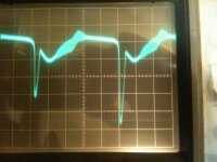
The 45 heater picks up noise at 5mV/div and the 5842 heaters at 0.5V/div. I have attached pictures taken with these settings (45 is on left). Unfortunately I doubt the scope has been calibrated. There is 100hz cycle evident in both readings - but hum is not evident from the speakers. Shouldn't the 5842 heater be more constant (<1V ac)? Also the 5842 voltage is 6.6V dc upstream of R3 and 5.4 dc downstream. R3 measures 2.6 instead of the desired 2.2. The 45 heater voltage is OK at 2.4V.
The other readings are fine with -200V bias, 280V B+, 175v for the 5842s and 28mA for the 45s.
Thanks, Henry
my TSE has a slight buzz from the speakers audible at 15 feet away, otherwise the amp sounds great. The buzz starts 4-5 seconds after turn on and doesn't change after hours. It is still there with the 5842's removed and is equal in both channels. If I move the amp around the room it remains the same. I have hooked up my old oscilloscope and tested the 45 heaters and the 5842 heaters. I am hoping someone can tell me if these readings seem reasonable.
The 45 heater picks up noise at 5mV/div and the 5842 heaters at 0.5V/div. I have attached pictures taken with these settings (45 is on left). Unfortunately I doubt the scope has been calibrated. There is 100hz cycle evident in both readings - but hum is not evident from the speakers. Shouldn't the 5842 heater be more constant (<1V ac)? Also the 5842 voltage is 6.6V dc upstream of R3 and 5.4 dc downstream. R3 measures 2.6 instead of the desired 2.2. The 45 heater voltage is OK at 2.4V.
The other readings are fine with -200V bias, 280V B+, 175v for the 5842s and 28mA for the 45s.
Thanks, Henry
Attachments
Last edited:
Hi, I got rid of the buzz, but the 5842 heater voltage is still fluctuating by 2V.
First the removal of buzz: I put 2.2uf Polys from B+ to ground on the output transformers, 1.2uf across the heater pins of the 45s, 220nf across the heater pins of the 5842s, a 10mF 16V cap in parallel with C1 and 4700uf 25V in parallel with C2. I did these all at once so I am not sure what fixed the buzz but I suspect it was the B+ caps or the 45 heater caps.
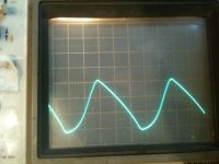
I attach a picture of the heater voltage of the 5842 read with DC setting 2V per division. The central division is 6V - so that voltage is still fluctuating wildly (and that is with a whopping 25mF suppression). It is all at the + side as the negative is smooth. On the other side of U1 there is still some fluctuation, but much less.
I am thinking it must be that one of the D1s that is faulty (STPS30L30CT). I will order two more and drop them in.
Henry
First the removal of buzz: I put 2.2uf Polys from B+ to ground on the output transformers, 1.2uf across the heater pins of the 45s, 220nf across the heater pins of the 5842s, a 10mF 16V cap in parallel with C1 and 4700uf 25V in parallel with C2. I did these all at once so I am not sure what fixed the buzz but I suspect it was the B+ caps or the 45 heater caps.
I attach a picture of the heater voltage of the 5842 read with DC setting 2V per division. The central division is 6V - so that voltage is still fluctuating wildly (and that is with a whopping 25mF suppression). It is all at the + side as the negative is smooth. On the other side of U1 there is still some fluctuation, but much less.
I am thinking it must be that one of the D1s that is faulty (STPS30L30CT). I will order two more and drop them in.
Henry
Attachments
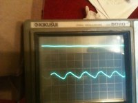
No that isn't it. I just realized that it would be 50hz if only one diode is working. It isn't. I just hooked up one lead to T1-7 (lower in the picture) and the other is on the + side of C1. C1 is definitely getting the peaks from both diodes. Perhaps C1 is blown and I actually only have that additional cap (ie only 10mF). Surly that is enough anyway? I am really confused now...
Attachments
I added 15mF (25mF total) and lowered R3 to .68R. The range is 5v to 6.6v centered at 5.8. I tried removing R3 altogether and that raised the voltage to 6.3 (ideal) but one of the 5482's began to glow brightly immediately after start-up. I guess this is as good as I will get it unless someone else has a suggestion.
Low drop out adjustable low noise regulator (340mV 40uV 3A TO-220)
LT1764AET#PBF - LINEAR TECHNOLOGY - ADJUSTABLE LDO VOLTAGE REGULATOR, 1.21V TO 20V 3A TO-220-5 | Newark element14
LT1764AET#PBF - LINEAR TECHNOLOGY - ADJUSTABLE LDO VOLTAGE REGULATOR, 1.21V TO 20V 3A TO-220-5 | Newark element14
6.7V input would suffice for 6.3V output in worse low mains hours. If using 6.1V to extend tube life, 6.5V input would suffice. To have 60mV > than spec as safety.
These are modern chips that need very little necessary drop across to keep regulating. They don't dissipate much when used close for Vin-Vout as a consequence.
These are modern chips that need very little necessary drop across to keep regulating. They don't dissipate much when used close for Vin-Vout as a consequence.
No Joy
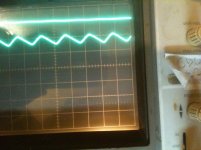
Hi, I tried adding a regulator but it is still not improved. If I go up to 6.3 (measured on my multimeter) there is about 1V fluctuation. The regulator did solve the inrush that caused one tube to glow brightly for a second after startup. Could you look at the schematic (called DIY) to see if I implemented the regulator properly?
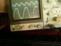
In the oscilloscope picture, each unit is 1 volt. The flat line is 6.3V from a lab regulator (as a control), and the jagged is on the 5842 pins. Why is it that my multimeter is reading 6.3V and the oscilloscope shows the voltage hovering around 5.3V?
I started off this thread with hum which I fixed long ago, but now I don't know whether it is fine to run these tubes 1V below recommended level. Any help is appreciated!
Hi, I tried adding a regulator but it is still not improved. If I go up to 6.3 (measured on my multimeter) there is about 1V fluctuation. The regulator did solve the inrush that caused one tube to glow brightly for a second after startup. Could you look at the schematic (called DIY) to see if I implemented the regulator properly?
In the oscilloscope picture, each unit is 1 volt. The flat line is 6.3V from a lab regulator (as a control), and the jagged is on the 5842 pins. Why is it that my multimeter is reading 6.3V and the oscilloscope shows the voltage hovering around 5.3V?
I started off this thread with hum which I fixed long ago, but now I don't know whether it is fine to run these tubes 1V below recommended level. Any help is appreciated!
Attachments
The 5842 is designed to operate with pure AC on the heater. Some residual ripple on the heater is normal since they receive unregulated raw DC.
The hum you experienced was still there with the 5842's removed, so they were not the hum source. If the amp is quiet without adding a regulator, then I would leave it alone. The DC voltage on the 5842 heater should be 5.5 to 6.3 volts. Most of the 5842's that I tested exhibit lower noise when run slightly below 6.3 volts. Slightly low heater voltage is better than slightly high for tube life.
Some multimeters will read the average value and some will read the peak when measuring a DC voltage with some ripple. Your scope is uncalibrated. I would tend toward trusting the meter. How do they compare when fed a pure DC source, like a battery?
The hum you experienced was still there with the 5842's removed, so they were not the hum source. If the amp is quiet without adding a regulator, then I would leave it alone. The DC voltage on the 5842 heater should be 5.5 to 6.3 volts. Most of the 5842's that I tested exhibit lower noise when run slightly below 6.3 volts. Slightly low heater voltage is better than slightly high for tube life.
Why is it that my multimeter is reading 6.3V and the oscilloscope shows the voltage hovering around 5.3V?
Some multimeters will read the average value and some will read the peak when measuring a DC voltage with some ripple. Your scope is uncalibrated. I would tend toward trusting the meter. How do they compare when fed a pure DC source, like a battery?
Hi,
Yes - the amp is dead quiet already. I am just not sure what voltage the tubes are seeing. The line at the top of the oscilloscope is from a lab power supply (that is how I calibrated the oscilloscope). My multimeter also sees this as 6.3v (ie it agrees with the lab power supply).
If the peak voltage is 5.5v is that enough for the tubes?
- Status
- Not open for further replies.
- Home
- More Vendors...
- Tubelab
- TSE buzz and PSU