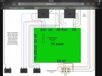
I am about to finish wiring my SSE and want to get my switches right first time.
Looking at George's wiring diagram, I can figure out that UL would be the connection between the left and middle pins of the switch. Triode mode would be with the middle and right pins connected.
But, it is less clear with the CFB switch. To me, it seems that left and middle pins result in zero feedback, while the middle and right pins connected would give cathode feedback.
Also on my Edcor OPT, one wire is labelled 8 ohms, the other "common." Which would I connect to the switch? I suppose I could do this empirically and choose the quieter of the options.
Thanks,
Charlie

Maybe this will help you.
An externally hosted image should be here but it was not working when we last tested it.
I posted this awhile ago for someone who had the same question... Hope it helps. Since you only have an 8 ohm tap, ignore the 4 & 16 ohm taps.
An externally hosted image should be here but it was not working when we last tested it.
Denny,
So the numbers on your diagram represent pins on the switches with 02 being the common pin?
If that is the case, then I have understood the UL correctly. With the CF there's something I am not quite getting.
Either way, given the solid volume from plain triode mode, I am actually wondering if I really need UL/CF at all - I'll ask this as a separate thread.
Thanks,
Charlie
The numbers represent the connection points on the board, but yes, 02 goes to the switch common... the middle connector. Both opt commons (white) go to connectors on one end of the switch, both 01 (ground) go to the other end of the switch. You are using a DPDT (double pole-double throw)switch like this?
DPDT Switch
DPDT Switch
- Status
- This old topic is closed. If you want to reopen this topic, contact a moderator using the "Report Post" button.
- Home
- More Vendors...
- Tubelab
- Getting the UL/triode and CFB switches right