Hi guys,
Well, I've moved on from blowing up my rectifier to something potentially more serious.
I had my SPP on the test bench, powered up for the purposes of measuring voltages, but without speakers attached. I noticed a humming noise getting louder, so I powered off. I assume that was some sort of oscillation.
When I powered the amp up again, this time with speakers attached, after a while I got a loud squeal of feedback. I've replaced my JJ EL84s with my backup set of Mullard EL84s. Two of the JJs rattle when gently shaken so I guess they are toast.
With the Mullards installed, I get slightly louder hum than I did with the JJs. Could that just be a difference between JJs and Mullards, or is the hum likely to be coming from elsewhere? Also, I'm still getting a ringing/feedback tone while playing music occasionally, more so after the amp's been on for a while. It's almost like it's resonant at a certain frequency.
I've ordered some replacement 12AT7s, and I'm hoping that'll fix the problem. Am I likely to have broken anything else? From what I've read, the OPTs could be damaged, but there was no visible sign of that.
Cheers,
Jon
I've taken some measurements. The resistance between the OPT B+ winding and the others is: Brown (plate) 152R, Brown/White (screen) 65R, Blue (plate) 173R, and Blue/White (screen) 64R. Both OPTs measure the same.
Having removed the PCB from the amp, and the tubes from the PCB, the resistors all measure good, except for R2 and R3, which won't give a stable measurement. My coupling caps measure 100nF, which is good, but all other caps measure fractions of a nF.
Given these measurements, it looks to me like its hopeful I haven't fried my OPTs, but it looks like I need to change most of the caps.
Does that sound like a reasonable course of action? It seems odd that I would have blown all except the coupling caps, and I thought that might be a measurement error, but it's repeatable.
Cheers,
Jon
Thanks guys. Yes, it's been a painful lesson, but one that I've learned nonetheless. I shall install some resistors across the speaker binding posts. I'll also try disconnecting the feedback - on the SPP that would mean connecting the OPT secondaries to the binding posts, and not to the feedback connectors on the PCB as I currently have them. Having said that, I've been using this amp for a few weeks without issue, which I would think would mean that OPT phasing was OK.
Do my measurements make sense? I'm going to order a set of caps, except for the coupling caps which seem to be OK. in the meantime I'll desolder the existing caps and then measure them again in isolation to see if they still look bad.
Do my measurements make sense? I'm going to order a set of caps, except for the coupling caps which seem to be OK. in the meantime I'll desolder the existing caps and then measure them again in isolation to see if they still look bad.
I removed all the caps from the PCB so I could test them reliably. It turns out my DMM only measures up to 100uF, so they might all be good. All the caps under that value measure OK. Is there any way I can test a 220uF cap on a 100uF meter?
Failing that, I guess I'll reinstall the caps and try the OPT phasing.
Failing that, I guess I'll reinstall the caps and try the OPT phasing.
I reinstalled the caps and reassembled the amp. Switched it on, and got a loud squeal. Swapped the plate and grid OPT connections on each OPT and now no squeal. Looks like it was incorrect phasing after all. Thanks Kevin!
Unfortunately one of my OPTs has picked up a fairly loud buzz in the meantime. Any ideas on what that might be, or is it just damage as a result of the speaker incident?
Unfortunately one of my OPTs has picked up a fairly loud buzz in the meantime. Any ideas on what that might be, or is it just damage as a result of the speaker incident?
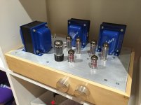
How close is that OPT to the power transformer or choke? Can you post pictures of the amp showing location and orientation of all transformers, and an interior shot of the wiring?
Check by substitution that you do not have a bad tube on that channel.
Look for cold solder joints and ground loops.
Does it still buzz with nothing connected to the inputs? (Try shorting inputs with nothing connected to them)
What sort of equipment do you have at your disposal for trouble shooting? Can you get a scope?
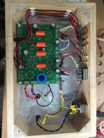
Kevin, here's a photo of the internal wiring. I'm struggling to attach more than one photo at the moment.
The photo shows the installed but unconnected mode selection switch (by way of clarification.)
I have background hum from both speakers equally. Slightly more than before the unconnected speakers incident, but in the meantime I have replaced the JJ EL84s for Mullards, replaced the JJ 12AT7s, and removed and reinstalled the caps.
I also have a buzz emanating from one of the actual OPTs - the one closer to the PT.
I don't have a scope I'm afraid, just a DMM.
Edit: this photo was taken before I reinstalled the caps (the Mylar C3 is now on the other side of the board) and swapped the plate/screen connections.
Cheers,
Jon
Attachments
Last edited:
Couple of things come to mind looking at this.
First is the wiring to the RCA jacks - is it shielded?
Second is the grounding arrangement for the RCA jacks, I assume there is a proper audio ground for them somewhere on the board, definitely should not go to the safety ground connection on the back of the IEC.
The ground connections to chassis should have proper crimp on ring terminals bolted down.
I'd seriously recommend shortening the insulated leads on all of those connectors so that uninsulated wiring is not exposed in such a way that an eventual short could occur.
The volume control shaft may want to be grounded.
What is the level of the hum on the outputs and is it influenced by the position of the volume control?
Wood box consider adding copper tape grounded to top plate around signal wiring areas.
Kevin, thanks for the advice.
The hum is pretty low - barely perceptible with my ear a couple of feet from the speaker.
The hookup wire from the RCA jacks -> input selector -> volume pot -> PCB isn't shielded. It seems some people prefer the 4-core shielded microphone cable, though that'll only cover two inputs. Otherwise, I'll find some shielded hookup wire. Either way, what's the best way to ground the shield? Should that be connected to audio ground?
That brings me onto the second point: I bought some copper tape from the hardware store - the stuff used to keep slugs off your garden! If I line the chassis with tape, applied so that it connetcs to both the deck and the bottom plate, should I leave holes for the RCAs and binding posts, so that they're not grounded to safety ground. Currently the RCA jackets are connected to safety ground, so I'll fix that. Also, the tape would ground the volume pot and input selector switch casings - is it OK to ground htem to the chassis, or should I also ground them to the audio ground.
When you say "I'd seriously recommend shortening the insulated leads on all of those connectors so that uninsulated wiring is not exposed in such a way that an eventual short could occur" I take that to mean that I should shorten the uninsulated part of the lead such as there is no exposed uninsulated wire. Sorry for being dense, but please confirm I'm on the right track!
I shall get some proper crimp on lugs for the chassis ground connection.
Cheers,
Jon
okcrum, thanks. I figured there would be a way to do it - just couldn't work it out!
I've found some shielded audio hook up wire - now I'm just trying to work out how I'm going to ground the shield. Presumably it is best to connect all the shields to audio ground at the input connections on the PCB - might just get a bit cramped and a bit messy.
I've found some shielded audio hook up wire - now I'm just trying to work out how I'm going to ground the shield. Presumably it is best to connect all the shields to audio ground at the input connections on the PCB - might just get a bit cramped and a bit messy.
I've found some shielded audio hook up wire - now I'm just trying to work out how I'm going to ground the shield. Presumably it is best to connect all the shields to audio ground at the input connections on the PCB - might just get a bit cramped and a bit messy.
If you're referring to shielded wire connecting your RCA inputs to the board then you can connect the shield to your
grounded chassis. What I did on my SSE was to solder a piece of regular hook up wire to the shields then attach this
wire to a bolt on the chassis. This worked fine for me.
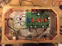
I've made a few changes now:-
Picture attached. I'll doublecheck my wiring and fire it up tonight, so will report back with how it sounds.
Cheers,
Jon
- Wooden chassis lined with copper tape
- Ground wires connected to chassis bolt via crimp connectors
- Shielded hookup wire from RCAs to input selector, shields connected to RCA jackets, which are grounded to the capper tape.
- All hookup wires trimmed such that there's no exposed conductor.
Picture attached. I'll doublecheck my wiring and fire it up tonight, so will report back with how it sounds.
Cheers,
Jon
Attachments
- Status
- This old topic is closed. If you want to reopen this topic, contact a moderator using the "Report Post" button.
- Home
- More Vendors...
- Tubelab
- SPP powered up without speakers. How much have I broken?