Hi folks,
I have gathered the parts for my SPP build, and now I'm planning my chassis layout. I'm planning an "inverted" build with the PCB mounted below an aluminium deck, mounted on wooden sides - pretty much the classic build with tubes visible and transformers mounted on the deck. I'll be using Edcor 25W OPTs and an Edcor PT.
I have a few questions:
Does it make sense to mount the higher output resistors on the top of the PCB so that the heat generated rises into the aluminium deck, rather than the PCB?
What thickness deck do people generally use?
I'm not planning on finalising the layout until I've had a chance to test the amp with the layout mocked up on the workbench. Are there any general guidelines I should stick to? For example, I gather the OPTs and PT should be at right angles.
Thanks in advance for any advice.
Cheers,
Jon
If you're mounting your pcb below the aluminum to plate you can place ALL of the resistors
on top of the board just as shown in the SPP assembly manual.
Just ensure there is sufficient clearance between the resistor surface and the top plate.
Install the resistors just as described in the manual.
For my SSE I used 5052 grade aluminum sheet of 1/10" thickness on a wooden base.
With 35 lbs. of transformers sitting on top there is no sagging.
Yes, you should mount the power transformer at right angle to the opt's.
I have built a few SPP's for Hifi and a couple as guitar amps. In most cases I put all the resistors and the other small parts on the top side of the board, and the big caps on the bottom. I think two were built with all parts on the top for display purposes.
I put the tube sockets in their holes but did not solder them, just bent a couple of pins so they didn't fall out. I then inserted the white ceramic resistors, and flipped the whole thing over on to the top plate which already had the tube socket and board mounting holes drilled. I then adjusted the ceramic resistors such that their cases were touching the top plate and soldered them. This allows the top plate to heat sink the resistors once the amp is assembled. R1 is the only resistor that gets warm and it doesn't need heat sinking unless someone (like me) decides to play guitar through the SPP at 20 db beyond clipping.....In that case the extra heat sinking won't hurt.
The chassis plate needs to be thick enough to support the transformers. 1/16 inch (.064) is fine for most OPT's in an amp that will just sit on the table. My guitar amps use a total of 17 pounds of transformers and will see some physical abuse, so I use 1/10 (0.100) inch aluminum.
I also learned not to use the screw terminals for connecting up the board on a guitar amp. After a few years of sitting on top of the speaker box, they get loose. Never had a problem in a HiFi amp though.
Thanks for your advice folks, and sorry to take a while to check back in!
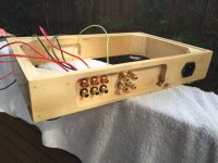
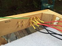
I've assembled the PCB with all the resistors on the top side. Right now I'm assembling the (wooden) chassis, which will have a 3mm aluminium top deck - see photos attached.
I'm now trying to get my head around how everything should be grounded. Is it reasonable to ground the RCA connectors' outer casings as shown in the photo, i.e. all soldered to an earth wire that returns to the centre pin of the IEC connector? I would then have separate ground connections from the mains ground pin to (a) the aluminium deck via one of the transformer mounting screws, and (b) the audio ground on the PCB via one of the input ground connectors.
I have three sets of input RCA jacks. With the casings grounded, I'm connecting the centre pins of the RCA connectors (i.e. left and right channel signal) via a 2P3T rotary selector to the volume pot tracks. The other end of the tracks would be grounded to the PCB input ground. The volume pot wipers would be connected to the PCB input signal connectors.
How do I ground the casings of the rotary selector and volume pot? Do I literally just solder a ground wire to the metal case?
Please let me know if I've got this all around the wrong way!
Cheers,
Jon
Attachments
- Status
- This old topic is closed. If you want to reopen this topic, contact a moderator using the "Report Post" button.