Finished assembling and wiring my Tubelab SE yesterday. This is for 45's, and i'm trying it with a 5U4GB rectifier because i have a surplus of those ( and i think i need more voltage drop ). Transformer is EDCOR and i'm using 260-0-260 windings. All caps / resistors are the stock value for the 45 tube instructions. Using an edcor choke with a DCR of around 80 ohm.
I get as far as the "plug in the rectifier tube" portion of the voltage testing, and my 5U4 starts arcing. I put another one in there...same thing.
I figure out that it's because i've grounded the 5v center tap, rather than just leaving it open.
Now things seem ok - I have about 340V B+ and my bias is like -270. This is WITH the 5842 tubes in there. When i adjust the bias trimpots for the 45 tubes, all it does is change the bias voltage from -270 to -262. I don't understand why there is such a small voltage variance for such a large trimpot.
Filament voltages all seem correct. 5842's have 175 on the plates. But i still have like 340 on the plates of the 45's ( way too much ) and -260 to -270 on the bias. ( measured with a voltmeter, relative to ground )
I was always under the assumption that plate voltage was going to be high if the tube wasn't actually consuming anything ( Because of an abnormal bias )... and when the bias is set correctly that plate voltage will probably go down. Am i wrong?
Also, the bias voltage off the FRED's seems to be like -300... why is this not dropping down to like -150 per the schematic, but staying up in this high -300 range? Could i have fried something with the 5U4 arcing incident from yesterday?
Theory at present is that the initial sparking 5U4GB issue ( from the center tap of the 5V being grounded instead of lifted ) put Q1/Q2 at full B+ and fried them. Will replace and see if that fixes it.
Tried everything else i could think of - making sure my trimpots were the correct part and value, lifting R7 and other resistors in the bias and making sure they measured the right value, etc.
There's just -300v on the bias supply, and down to maybe -280 at the top of R7. It's over 100v more than it should be.
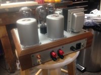
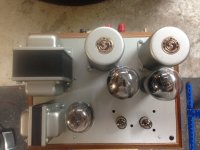
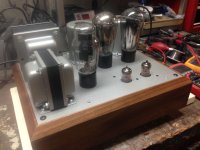
Some pics of my project.
I used Edcor PT and Choke, James 6113 OT's, Hammond 10x13" walnut chassis w/aluminum top and bottom plates ( and feet, not pictured), and painted all of it with 3-4 coats of Rustoleum Hammerite Satin Nickel.
I ended up drilling holes through the walnut on the back, and mounting that 22 gauge steel plate, with all the jacks / switch / IEC / fuse mounted to it, and painting it to match. I'm happy with the results.
Attachments
Last edited:
replaced Q1 and Q2 with new chips. Things are a little better, but still not usable. Bias voltage at #45 tubes is now around -230V.
Does anyone see a problem with me modifying R7 to a lower value resistor to bring down the voltage so its at -150v? I have way too much bias voltage and i have to figure out how to shed it.
Does anyone see a problem with me modifying R7 to a lower value resistor to bring down the voltage so its at -150v? I have way too much bias voltage and i have to figure out how to shed it.
This continues to bum me out.
Swapped the 100k R7 bias resistor ( the one that is supposed to set the bias level at around -150v ) with a 25k and it brought the bias voltage down to -220. Still way too much.
I don't understand why the two bias trimpots for the 45 tubes only adjust the voltage 10v total.
I'm ready to throw this thing in the trash.
Magnetmaz,
Don't give up....the results will be worth the effort. c4 in the power supply will adjust the b+ voltage to the 45s. I needed a pretty small cap in this spot to get the b+ down to a reasonable level for the 45 tube.
My build also ended up with a more negative bias voltage then it was supposed to have. I left it as is and went ahead with the build. The amp worked fine and sounded great. When I went back and messed with the resistors in this part of the circuit I got the negative voltage where it was supposed to be the amp didn't sound as good to me so I went back to having the negative voltage about where you are now.
when setting the bias you are looking to get about 30milliamps across r18 and r29. this will be .3vdc if you have 10ohm resistors in this position. The single turn pots are touchy...it takes some patience to get the setting just right.
Hope this helps,
Evan
If you want to send me the board, I can take a look at it. With only ~10v adjustability, something is going on with the divider string where it isn't working as it should. Doesn't really matter that the overall bias supply voltage is 'high' - that's not the problem. The problem is you've no adjustment range.
- Status
- This old topic is closed. If you want to reopen this topic, contact a moderator using the "Report Post" button.
- Home
- More Vendors...
- Tubelab
- Tubelab SE bias problem