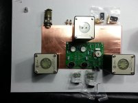
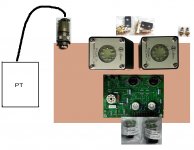
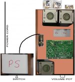
Figured I would share my idea for the layout of the amp (PS will be on a separate box). Not a great picture; sorry!
I am aiming to have equal distances between each 300B tube and the respective OT. The OT's will mount in the corners to take advantage of the additional bracing there and the choke will mount central rear. Once I test the plate on the wooden base (arriving Wednesday) I can determine whether I can pull them in from the sides a bit if it looks like it will hold up okay.
The switch and volume controls are at the front and the various connectors at the rear including the Amphenol umbilical connector.
I will likely raise the 5842's on socket savers as the board will be suspended 1.25" below the copper plate.
I realise this will make the amp front heavy when moving it but being as it isn't a Walkman it won't be going out much
Anyone see any issues with this proposed layout? The PS will be two feet away by the way.
Attachments
I'd be concerned about restricting airflow with boxing the tubes in. The sockets on the TSE board are very close together with 300B's in them.
Why not put all the tall stuff on the bottom of the board so you can mount it closer to the top plate so you don't need socket savers or some other means to raise the sockets? It's a very clean look, and it's not too difficult to get the heater regulator to cooperate.
Why not put all the tall stuff on the bottom of the board so you can mount it closer to the top plate so you don't need socket savers or some other means to raise the sockets? It's a very clean look, and it's not too difficult to get the heater regulator to cooperate.
An externally hosted image should be here but it was not working when we last tested it.
An externally hosted image should be here but it was not working when we last tested it.
Even, you stole my choke! Where do you suggest the choke goes; bottom left corner?
My power line was probably further away from the OT's in my layout than yours (I thought) though the choke is nearer to the power lines than on yours (assuming you return it to the pictogram). Is there any reason to keep the incoming power lines away from the choke? If not, using my layout, I could simply bring the power lines in through the center of the case directly under the choke.
JP; I like what you did but I decided to mount the heatsink-attached stuff on top which I will vent through cuts in the chassis (I like the way you did your cuts). The caps are all going underneath so the 1.5" is purely to allow for the heatsink-attached stuff.
I may not use the tube savers depending on how the 5842's look; I haven't calculated the amount they will be visible.
Thanks for the feedback chaps.
Yes. Or put it with the PT like I did.Even, you stole my choke! Where do you suggest the choke goes; bottom left corner?
The power tabs are on the left of the board so having the power connector to the left of the chassis and input lines to the right is a good idea (power line and interconnects should be as far away from each other as possible).My power line was probably further away from the OT's in my layout than yours (I thought) though the choke is nearer to the power lines than on yours (assuming you return it to the pictogram). Is there any reason to keep the incoming power lines away from the choke? If not, using my layout, I could simply bring the power lines in through the center of the case directly under the choke.
So following on from the theme of keeping Ac away from signal; should the individual or collective bunch of wires (teflon coated 18AWG) be shielded in some manner or is that not important?
Currently my plan is to run them through the amphenol 14pin with the ground wire running down the middle and the whole bunch sleeved with braided pvc.
Currently my plan is to run them through the amphenol 14pin with the ground wire running down the middle and the whole bunch sleeved with braided pvc.
I will hold off till I see how the build comes together and if hum is present it will be one of the things to check.
Did you twist pairs of cables together in your umbilical or just run them straight through? I know there is value in twisting inside the main chassis but my search hasn't been fruitful on the benefits of twiting in an umbilical.
You can imgine the kind of Google results I got when searching "twisting cables umbilical"
Thanks.
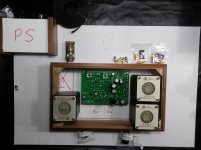
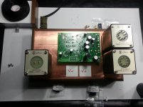
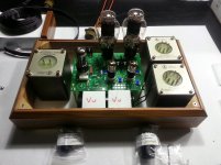
What about this (obviously the PCB is flipped)?
I may orientate the choke to be the same as the OPT's.
The depth of the chassis is not enough to comfortably have the PCB in front of the OPT's as in an earlier suggestion so they need to move.
There is insufficient room on the PS box to have the choke so it needs to stay on the main chassis.
I want to put a couple of VU's in for bias measurement.
The PS will be further away obviously.
See any issues?
Attachments
- Status
- This old topic is closed. If you want to reopen this topic, contact a moderator using the "Report Post" button.
- Home
- More Vendors...
- Tubelab
- Proposed layout