Hello,
I have had my Simple SE up an running now for a few months and decided to do a few upgrades. By the time I collected the new resistors and caps I figured I could build a whole new one if I threw in a couple of CCS's and some new sockets. I thought I would build it point to point, really, just for the fun/learning experience of it. DO I expect the sonics to improve? I can hope, can't I? DO I think they may get worse from poor circuit lay out? Perhaps, but I want to try it and see.
Just a question before I dig into this (most parts will arrive early next week):
Are there any particular concerns I should address for grounding in my point to point build? I sorta figured I would just emulate what the PCB does.
Any input is appreciated. Thanks!!
Super! Thanks. Those are both great. Lots of pertinent info there.
This brings up a question:
Would it be good to add another layer of filtering (RC) for the driver section? (This is discussed in the Valvewizard.co.uk link.) Or would that be unnecessary?
Also, I am going to use two 50uf ASC Motor run caps in Parallel for the second stage in the B+ filter. Could I use a short busbar connecting the two ground terminals as the star point if I do star grounding? I have done this before in Solid State amps.
Thanks again!
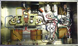
I've not built a SSE, but it is similar enough to the attached schematic. You can see the additional filtering for the driver tube. This is a variation of the Abdellah amp. Some have used LC as shown, others RC. Try it with and without and see.
I would think you'll be ok with ground point as you describe.
I have also attached the layout that I used for the amp that matches the schematic. Maybe it will help.
I would think you'll be ok with ground point as you describe.
I have also attached the layout that I used for the amp that matches the schematic. Maybe it will help.
Attachments
- Status
- This old topic is closed. If you want to reopen this topic, contact a moderator using the "Report Post" button.