Though I started the build over the past weekend and didn't snap any pictures of stuffing the board or punching holes in my top-plate, I thought I'd share some pics of the build thus far. Big thanks to Tubelab for this easy to follow design!

Edcor parts arrived about 3 weeks after ordering (much quicker than the quoted 5 weeks). The power transformer is the XPWR155, the OPTs are GXSE15-6-5k (to be used with 4 or 8 ohm speakers), and the choke is a 2H 200ma Edcor. Motor-run cap is also on the right.

Kind of a blurry pic, but here's the chassis I'm using. When it's not in pieces (all over the dining room table) it's very good looking and part of the reason I started this build. The enclosure is about 8" x 12" x 2" so this will be a tight fit. That said, a compact amplifier was part of the goal (wife's orders). Large holes were cut with a Harbor Freight punch. They're all a bit larger than the sockets and not perfectly centered. We'll see how well hidden this fact is when everything is put together.

Back panel with recommended grounding wires per Tubelab website. The jacks are all insulated so the chassis will also be grounded individually via one of the transformer mounting screws.
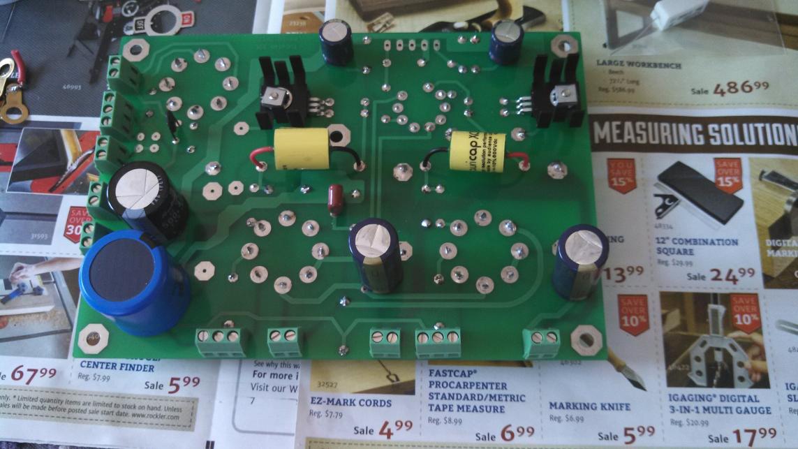
And here's the good stuff! Notice I left off the connectors for the input. I'm going to be using a Blue Velvet and the clearance is already going to be very tight at the front of the board. I'll wire it directly to the board.

Board topside. The eagle eyed among you will notice that there's no R24. That's not intentional, I assure you. I'm waiting on the missing resistor from Digikey; should be here soon.
Still to do:
-assemble chassis with board to determine the on/off switch and pot location (input switch may be installed later once amp is working)
-get some solder tabs for those binding posts
-get that R24 installed!
-assemble chassis and wire it all up
-pray
-if amp works, listen for a while and then add the UL and CFB switches
Edcor parts arrived about 3 weeks after ordering (much quicker than the quoted 5 weeks). The power transformer is the XPWR155, the OPTs are GXSE15-6-5k (to be used with 4 or 8 ohm speakers), and the choke is a 2H 200ma Edcor. Motor-run cap is also on the right.
Kind of a blurry pic, but here's the chassis I'm using. When it's not in pieces (all over the dining room table) it's very good looking and part of the reason I started this build. The enclosure is about 8" x 12" x 2" so this will be a tight fit. That said, a compact amplifier was part of the goal (wife's orders). Large holes were cut with a Harbor Freight punch. They're all a bit larger than the sockets and not perfectly centered. We'll see how well hidden this fact is when everything is put together.
Back panel with recommended grounding wires per Tubelab website. The jacks are all insulated so the chassis will also be grounded individually via one of the transformer mounting screws.
And here's the good stuff! Notice I left off the connectors for the input. I'm going to be using a Blue Velvet and the clearance is already going to be very tight at the front of the board. I'll wire it directly to the board.
Board topside. The eagle eyed among you will notice that there's no R24. That's not intentional, I assure you. I'm waiting on the missing resistor from Digikey; should be here soon.
Still to do:
-assemble chassis with board to determine the on/off switch and pot location (input switch may be installed later once amp is working)
-get some solder tabs for those binding posts
-get that R24 installed!
-assemble chassis and wire it all up
-pray
-if amp works, listen for a while and then add the UL and CFB switches
Thanks, kevin.
One input jack will be connected to the IEC, so the board will be grounded by way of the input ground via the volume pot. I will also run a ground from the IEC to a bolt on the chassis. This seemed to me the simplest way to assure I've grounded both the board/inputs and the chassis without creating any loops.
Is there an advantage to running a ground from the IEC to a bolt on the chassis and running the ground from the input jack (which grounds the board) to the bolt instead of the IEC?
Do not connect any of the input jacks directly to the IEC, ground the chassis and from that point run back to a common ground point in the amplifier (I assume there is such a point you can identify) and reference ALL external signal grounds to that point.
The second approach may work ok provided that is the only connection between the amp signal ground and the safety ground.
There should be a lot of detail on these and similar issues in the tubelab forum. Solutions that are known to work..
The second approach may work ok provided that is the only connection between the amp signal ground and the safety ground.
There should be a lot of detail on these and similar issues in the tubelab forum. Solutions that are known to work..
If you can provide a single universally agreed upon approach to the art of grounding, I'm all ears
This grounding scheme is based primarily off of the tubelab website wiring diagrams and asking a couple others that have built amplifiers. Alternatively, I could omit the ground at the input jack and ground the board via one of the screw-down connectors, but when asking on the forum no one seemed to respond to that.
See about halfway down this page for the wiring I'm planning on (alternatively I could ground the board at the same terminal as the HV center tap):
Wiring Diagrams | Tubelab

Gettin closer! The pot is going to be a verrrrry tight fit with the board, but it should work. I did install a ring terminal on one of the power transformer bolts and I think I will go ahead and take Kevin's advice to just ground everything to it (and it to the IEC). In the end, I think this will give me the shortest wires required for grounding.
The input jacks are insulated, so I'll ground the board via one of the screw down terminals (likely the unused 2nd half of the connector to which the HV center tap is grounded). This will go to the bolt along with the grounds on the speaker posts (the amp will be non CFB to start). The bolt will be grounded to the IEC ground.
By the way, this thing is getting heavy! My final resistor will be here today or tomorrow so I should be able to install the board and wire it all up very soon.

Here she is, standing atop her vanquished rivals. Almost brings a tear to the eye.
Next up will be UL and CFB switches.
Also, I need to install an R2. I inadvertently bought a 150ohm instead of a 150kohm. Because it's a bleeder resistor, and R3-R4 serve a similar purpose, I omitted it while I wait on the part. Glad I noticed before I started blowing fuses! That would have been a bit hard to track down.
Anyone have any ideas for a trim ring for the 12AT7? The hole is a bit large and off-center (the rest of them are hidden by the octals). I'm thinking something like this guy:
MUSE TU 20 Russia EH6922 Smallest Tube Preamp Headphone Amplifier BLack-in Headphone Amplifier from Consumer Electronics on Aliexpress.com
Yes, no hum that I can detect! Thanks for the advice on grounding. I did end up grounding the board (via the HV CT screw-down) and binding posts to a bolt on the PT and connecting that to the IEC. The other way may have worked fine, but I suspect this wiring was cleaner than it otherwise would have been.
This is my first hifi SE and so far I'm sold! I own and have worked on SE guitar amps and the simple little 5 watters are always some of my favorites. I'm looking forward to some serious listening time.
This is my first hifi SE and so far I'm sold! I own and have worked on SE guitar amps and the simple little 5 watters are always some of my favorites. I'm looking forward to some serious listening time.
socket cover
One of these might work around your 12at7, might be too big. Closest I have seen to what you want.
One of these might work around your 12at7, might be too big. Closest I have seen to what you want.
After a few days of ownership, I've got a couple of observations.
I have no hum at the speakers without my turntable/source powered up unless I max the volume and put my ear to the speaker. I'm totally happy with performance with respect to this. I have noticed some 'buzzing' from the amp when running though. I assume this is something mechanical related to my PT. It's not audible from my listening seat or from more than a couple feet away, but I may try some thicker washers on the PT/choke and cranking down on the PT bells.
The first time my wife turned on the amp, she blew the fuse! She sort of switched it on and then off very quickly (just trying the switch, I guess). Without having allowed the tubes to warm up and start conducting, I would guess that this just created a spike in the PS caps that had nowhere to dissipate once the amp was switched off? Is that close? I'm not worried, just interested in exactly what causes this. It should be noted that I do not have an R2 installed as I didn't have the correct value on hand (that will be rectified once R2 arrives). It's a bleeder resistor, so that probably contributed to the fuse blowing there. Amp works fine after replacing the fuse.
All in all, I'm still bowled over by the sound. Really a fantastic little amp. I'm a little scared about doing any type of modification that would change it, but I'll try installing a CFB and UL switch at some point in the future.
I'm assuming she actually switched it on/off/on as imle that is usually what blows the fuse, and relates to the induced emf from the collapsing magnetic field and the phase relationship of that to the line voltage when the switch is cycled. (If they are not close a lot of current flows) Possibly if it really was on/off perhaps it arced across the switch if sufficient current flows perhaps this could blow the fuse.
It could have been on/off/on, though we didn't listen to it at that moment and I didn't see that the fuse was blown until later. I'll sit her down and go through Tube Amp 101 tonight
Maybe I'll tell her the tubes are the big glass things on top and that now I have to get another set...
Maybe I'll tell her the tubes are the big glass things on top and that now I have to get another set...
It could have been on/off/on, though we didn't listen to it at that moment and I didn't see that the fuse was blown until later.
Definitely a "no no" with tube rectification.
I'll sit her down and go through Tube Amp 101 tonight
Go idea.
Maybe I'll tell her the tubes are the big glass things on top and that now I have to get another set...
Yes, they are now permanently damaged from her actions.
jeff

- Status
- This old topic is closed. If you want to reopen this topic, contact a moderator using the "Report Post" button.
- Home
- More Vendors...
- Tubelab
- Soda's Tubelab SSE Build