It's been a while since I've done a project and I'm feeling the urge to dig into the parts bin.
I had originally intended to build out a screen drive amp using all sorts of oddball tubes, but couldn't get it off the ground. So to make progress I've decided I need to scale back the project and effectively do a bone-stock copy of the Universal PP Driver Board | Tubelab schematic. The only part I'm missing is the 5965 tube.
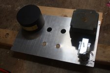
The hardest part of all this will likely be mounting the massive Tektronics power transformer.
Time to drill out the plate and mount the sockets.
I had originally intended to build out a screen drive amp using all sorts of oddball tubes, but couldn't get it off the ground. So to make progress I've decided I need to scale back the project and effectively do a bone-stock copy of the Universal PP Driver Board | Tubelab schematic. The only part I'm missing is the 5965 tube.
The hardest part of all this will likely be mounting the massive Tektronics power transformer.
Time to drill out the plate and mount the sockets.
The only part I'm missing is the 5965 tube.
The only reason I chose that one is the fact that I had several hundred of them. It is similar to the 12AU7, but a better choice would be a 12BH7, 6CG7, or a 6SN7.
have not designed any thing new in several years, so it's about time. I have picked up near where I left off on driver boards. I have a board that is similar to the one you are copying, but it uses 6SL7's and 6SN7's. I also have a new design that can use any of the 9DX based tubes like the 6BA8. The triodes are the LTP first stage, and the pentodes are the LTP second stage.
I have been using the new board for driving the screen and control grids simultaneously for big power out of small tubes. The experiments have been posted in this thread:
http://www.diyaudio.com/forums/tubes-valves/237808-show-me-your-screen-drive-circuits.html
I will try to post a schematic this weekend.
I'd rather use a 6CG7 myself because I've got some. I was hoping to use a 6J6 and 7W7's, but my brain doesn't have spare cycles to figure things out, so I have to just copy.
I've got a stash of the 2SK2700's. The OPT's will be about 2200 ohms. I'm hoping for a solid 100w.
Thx for the link. Looks like interesting reading.
I've got a stash of the 2SK2700's. The OPT's will be about 2200 ohms. I'm hoping for a solid 100w.
Thx for the link. Looks like interesting reading.
Hey George, any chance we can get a peek at your dual-drive circuit? ")
I just need to find some wire for the heaters and I should be ready to put the circuit in. I changed my mind and will use 6GV5's and put in sockets for 4 of them, but I'll initially use only two tubes for output.
I just need to find some wire for the heaters and I should be ready to put the circuit in. I changed my mind and will use 6GV5's and put in sockets for 4 of them, but I'll initially use only two tubes for output.
Just when I get caught up to the point where I started building stuff again, life throws me another one. It looks pretty certain that my 41 year career with Motorola will end at the end of the year. With Mot, Blackberry, Foxconn, and others all dumping engineers on the market here, it's time to leave Florida. I don't know what next year will bring, but it will be different, that's for sure.
I was working on this thing pretty steady until about a month ago, then nothing. I enclosed the schematic of the driver board. Before I get a dozen questions, I will try to explain it a bit.
About 10 years ago I threw together a P-P amp using 300B output tubes. They need lots of drive so I took a wild guess and pasted together several circuits and a few of my own ideas and laid out a PC board. I used rock bottom junk parts since I didn't even expect it to work. The results were outstanding. It is the only amp I still have from that era even though it no longer works (Blown power supply). The driver board is two stages, both LTP's. This configuration seems to work great and allows for a lot of experiments. The first stage was a 5751 tube in LTP. The second stage was sort of an LTP created by taking two SRPP stages made with 6CG7's and tying the cathodes of the lower tubes together. All of my later P-P driver boards have evolved from this concept including this one.
The driver circuit used in the 6AV5 screen drive amp, and the one used in the 6L6GC in AB2 amp are similar they used one triode LTP driving a second triode LTP. The tube compliment changed to match the gain and drive voltage I needed at the moment, and also was influenced by whatever tubes I had around at the time. For G1 drive on just about anything except maybe 300B's a 6SN7 driving a 6SN7 worked great. For a bit more gain the first tube became a 6SL7. With miniature tubes the first tube was a 6CG7 or a 5751 and the second tube was a 6CG7.
When negative feedback is used, especially with output tubes that need lots of drive, like transmitter tubes or screen driven sweep tubes, even more gain is needed. I experimented with making one of the LTP's with pentodes. Two breadboards later I decided that the pentode should be in the second stage. That led to the circuit you see here. This is not meant to be the final design, but it works well enough that I made 3 copies. Only 1 has seen power. I am still tweaking parts values and trying different output tubes.
This is the Eagle schematic for the driver board itself. I don't have a schematic for the complete amp, or the power supply. For now it is all powered with bench supplies.
The first stage is a triode LTP. The LED's and resistors form a regulated +/- 3 volts of offset to the undriven input. This is used to null out the inevitable unbalance in a direct coupled circuit. It is too sensitive and hard to adjust. A 1K resistor across the IN_2 terminals fixes this. R7 is now a pot to set the tail current. This is needed for tube rolling. Set the current and plate load resistors for about 100 volts on the plate to make the pentodes happy.
The second stage is a pentode LTP. It is direct coupled to the first stage. R44 is a pot to adjust tail current. D1 is a zener that sets the screen voltage. I currently have a 150 volt 5 watt part in there and it has worked for every tube I tried. The pot on the screen grids doesn't do much and may be eliminated. The plates are fed from the same B++ source as the output tubes. I have been to 550 volts with the 6BA8's and nothing blew up. My power supply goes to 650 volts when I get bigger output tubes.
The third stage is a typical mosfet follower for driving screen grids, or control grids in AB2. The sources are tied directly to the screen grids of the tube being driven. A resistor divider is wired between the screen and the negative supply rail, with the tap going to the control grid. The values are adjusted such that the control grid never goes positive. Some experimentation is needed here. I currently have a 10K 5 watt resistor from G2 to G1, and a 2500 ohm 5 watt resistor from G1 to B-. These values were scientifically derived based on what I could find digging through a box of resistors, so there has to be room for improvement. R5 and R3 were removed from the PC board since they did nothing but waste current. R15, R36, R35 and R37 are for feedback experiments and are not populated at this time.
The negative supply has been tested from -40 to -100 volts. any more negative voltage would require bigger heat sinks on the semis, especially IC3. You need about 275 volts or more on the B+ supply this is mandated by the 100 volt plate voltage on the triode, which sets the voltage on the cathodes of the pentodes PLUS the 150 volts for the screens PLUS the drop on R32. Trade offs may be needed for supplies under 300 volts, but the circuit works up to 500 volts. Small heat sinks are needed for the fets and CCS chips. IC3 gets the hottest and starts smoking if I set the current or negative supply too high.
I have about 15 different tubes that fit this board out of the 22? possible candidates. The 6BA8 is in there now because it has the lowest gain. I may switch to different tubes when I start experimenting with feedback.
Attachments
George, Very sorry to hear about the job! Between my wife and I, we've gone through 5 layoffs in the last 6 years. It can be pretty stressful! I guess for us the good part is that not only have we landed in better jobs each time, but after moving from Oregon to the midwest for several years, we were able to come full circle back to Oregon. So you never know, Florida might be on the radar down the road. Hang in there!
- Status
- This old topic is closed. If you want to reopen this topic, contact a moderator using the "Report Post" button.
- Home
- More Vendors...
- Tubelab
- Universal PP build