A question for you, I have had the SE running all day so roughly 8hrs, voltage across R30 is 360/370 all of a sudden the sound fades down and the voltage across R30 is 414v, I should mention the R30 resistor could be a 120k about 2W not sure it was salvaged one. I turned off the amp for a few minutes and then on again it works for about 10 minutes then the same thing happens. Could this be the resistor failing? its not burning, actually nothing smells funny. or could it be the chips Q1 and 2 the solder joins look like they have been hot.
anyways look forward to you comment
cheers
Luke
anyways look forward to you comment
cheers
Luke
Hi,
If you could post a link to a schematic...")
Then we can comment..
Is it this one?
http://www.tubelab.com/Simple_SE_schematic.htm
Regards
M. Gregg
If you could post a link to a schematic...
Then we can comment..
Is it this one?
http://www.tubelab.com/Simple_SE_schematic.htm
Regards
M. Gregg
Last edited:
Could be,
A bias problem..if the power tubes stop conducting the voltage drop across the R4 or choke will decrease due to less current drawn.
Have you checked the bias when it fails?
Ie what is the voltage across R18/R29 normal and fail condition?
Its on the HT (B+) so be carefull..I guess you are used to working on this amp?
Regards
M. Gregg
Last edited:
No I have not checked that. I will put the multimeters in tomorrow and see what is happening.
cheers
Also,
Check the voltage across the bias trim pots and see if there is any change.
You need to check the valuse around the trim pots are to the drawing spec unless this amp has been running for some time ie (months) is this a first run?
Regards
M. Gregg
Actually thinking about it more, would both channels simultaneously fade out if it was the bias?
If somethng happens to the bias voltage yes its got to be common to both channels..so it could be the power supply..
I assume you have checked B+ is ok AT THE TUBES?
The voltage across R30 would seem to say you have B+..
Regards
M. Gregg
Last edited:
You need to work back from the power tubes..
Test the bias first if thats ok
then test voltage across the cathode resistors of the pre amp tubes..
See if you have conduction..
From these readings you can see if the power tubes are conducting or not and if the pre section is conducting..
Remember that bias can shut down a power tube..so the readings before the fault and after are important..
Remember to have a load on the output Tx..to protect the Tx..
Regards
M. Gregg
Last edited:
It could be that,
The IC on the first pre tube load is shutting down on over heat..
You will know this from the value across the cathode resistor..
just check the PSU is dead before you touch anything take care!
One other thing watch for red plating..if you get any tube plate start to glow red power off<<this is not the heater..LOL
This should not happen as long as current though a tube is within spec..again you will know this from the bias setting..
If bias is OK current is OK..
Don't want to tell you things you may already know...ie bias current is common for the power tubes what goes though the resistor goes through the OP tube..and op Tx.
Calculate current R18 (voltage across it divided by value of R in ohms = current)...this is common (the same) as power tube current.
Regards
M. Gregg
Last edited:
Hi,
Payload I think you hit the nail on the head! I was pondering the problem all day yesterday, flinging emails to a friend of mine and we came to the same conclusion. The heat sink on the U1 volt reg is not big enough! I was worried this may become a problem during the initial construction.
So I need a heat sink that will fit note the chip is in backwards because it is on the underside of the board.
Any suggestions?
I also swapped out the R30 for a proper 120k 3W.
I had the amp running all day yesterday and it behaved well, however it is not in a chassis yet. No doubt that will compound any heat dissipation problems.
R30 is the bleed resistor across the main reservoir cap. It's purpose in life is to bleed off any charge on the cap when you turn off the amp. If the voltage across this resistor rises dramatically (as is the case for you), this means that the load current (i.e. the current the amp draws) has dropped dramatically. This would be the case if the filament regulator has shut down as this would cause the power tubes to no longer conduct current.
The filament regulator will need a heat sink. If you are using a metal chassis, you may be able to use it for the heat sink. Just remember to put a thermal washer between the regulator and the chassis. It may be a bit tricky to mount if you're having the tubes poke through the top of the chassis, but you may be able to bend the leads on the IC at a right angle and get the regulator in from the top side of the board. This would allow you to mount it to the top of the chassis (which I assume is metal).
You're not the first to get bit by this, by the way. Most people tend to grossly underestimate the amount of heat sinking needed to dissipate even a few watt.
~Tom
yes its easy to underestimate thermal dissipation, I dont know much about it to be honest, I sure there is some kind of formula.
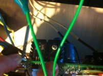
The difficulty is with this component is is surrounded by the caps. I have contemplated folding some aluminum like a bracket/conductor that could attach to an internal wall of the chassis i have designed. would that work?
heres a pic, note my finger is hovering over U1
The difficulty is with this component is is surrounded by the caps. I have contemplated folding some aluminum like a bracket/conductor that could attach to an internal wall of the chassis i have designed. would that work?
heres a pic, note my finger is hovering over U1
Attachments
Power dissipation: Pd = (Vin - Vout) * I
Temperature rise over ambient: Delta T = Pd * Rth where Rth is the combined thermal resistance of the device plus heat spreader.
Now although Rth can be found in data sheets, it is academic because your situation is such that the whole thing is surrounded by other heat sources and convection blocked by other components. Also ambient inside the box may be much higher than room temp due to the tubes.
I'd probably take the regulator out of the board, attach it to the metal wall of the box, and connect it with wire to the PCB. In case of wires a 100nF cap directly soldered between regulator output pin and gnd pin to prevent oscillation due to parasitic wire inductance.
If you don't want to use the wall, mount a bigger heat spreader (2x or more) in a convenient spot, again w/ wires and cap.
In any case make shure the regulator is mounted electrically isolated.
And put a bit of thermal grease between device and heat sink / wall.
Just for interest,
Your heat sinks are very close to the electrolytic caps...the life of the caps is dependant on ambient heat...
You still need to prove what is happening...why is it shutting down?
You need to address the issue not try to second guess it and hope for the best..Look again at the heat sinking if its a wooden chassis then bolt the Heatsink on the outside and remember to earth it. I prefer mica and paste with B+. Each to his own I guess. You can use aluminium angle and mount the heat sink next to the board it just depends on logistics of the build.
You need to plan something like this, take care of where components are mounted..Gook Luck hope it all works out!
Regards
M. Gregg
- Status
- This old topic is closed. If you want to reopen this topic, contact a moderator using the "Report Post" button.
- Home
- More Vendors...
- Tubelab
- Tubelab SE problem