Just for interest,
You can bolt a heat sink to the outside of the chassis and use compound between it and the metal chassis then bolt the components inside and use compound etc the heat will transfer through the chassis and the heatsink..
Remember to keep the components on the inside of the chassis they are at B+<<<
If its a wood chassis then again mount the heatsink outside and connect aluminium angle to the heat sink bring it through a slot in the wood and mount components on the angle..again remember to earth the heatsink.. (heatsink will be outside and components inside the chassis..)
Space the heatsink off a wood chassis by a few mm. I have been known to use double mica and paste on components connected to B+..depends on the voltage level..
Catch you laters..
Regards
M. Gregg
You can bolt a heat sink to the outside of the chassis and use compound between it and the metal chassis then bolt the components inside and use compound etc the heat will transfer through the chassis and the heatsink..
Remember to keep the components on the inside of the chassis they are at B+<<<
If its a wood chassis then again mount the heatsink outside and connect aluminium angle to the heat sink bring it through a slot in the wood and mount components on the angle..again remember to earth the heatsink..
(heatsink will be outside and components inside the chassis..)Space the heatsink off a wood chassis by a few mm. I have been known to use double mica and paste on components connected to B+..depends on the voltage level..
Catch you laters..
Regards
M. Gregg
Last edited:
Hi M Gregg,
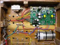
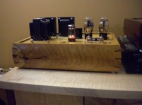
The chassis is 2mm aluminum, i have designed the inside with two barriers partially to section/screen off the outputs and the power supply and also to provide extra strength. The tubes stick out the top. I was thinking that it would be possible to bolt the chip to the inner wall there is enough room to put a really big heat sink in then.
Just to clarify I am not sure this is the issue but it does have the potential. I have all bias points on multi-meters and just wait for it too happen again. This is the fun bit right? The next opportunity for such a long run in is the weekend.
cheers
Luke
The chassis is 2mm aluminum, i have designed the inside with two barriers partially to section/screen off the outputs and the power supply and also to provide extra strength. The tubes stick out the top. I was thinking that it would be possible to bolt the chip to the inner wall there is enough room to put a really big heat sink in then.
Just to clarify I am not sure this is the issue but it does have the potential. I have all bias points on multi-meters and just wait for it too happen again. This is the fun bit right?
The next opportunity for such a long run in is the weekend.cheers
Luke
I just saw this thread. It sounds like the filament regulator is the issue, but it is easy to confirm. You can attach a voltmeter across the filament of the output tubes and observe the voltage, or you can simply observe the filaments inside the output tubes. If the voltage or the filament glow goes away when the sound fades, then the regulator is entering thermal shutdown. You can test this by pointing a fan at your heat sink and the sound will return as the heat sink cools. I have seen builds that work OK for a while and then begin to exhibit this problem. It seems that the thermal compound degrades a bit with age.
The heat sink that is shown in your picture is marginal for 45 tubes and not big enough for 300B's. I have been using heat sinks reclaimed from old computers for my builds. The old 486 and Pentium 1's have heat sinks that work well.
A 2mm aluminum chassis is good too.
edit: I just realized that your name and location sounded familiar. I sent your board on Friday.
Hi,
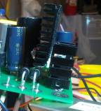
Payload I think you hit the nail on the head! I was pondering the problem all day yesterday, flinging emails to a friend of mine and we came to the same conclusion. The heat sink on the U1 volt reg is not big enough! I was worried this may become a problem during the initial construction.
So I need a heat sink that will fit note the chip is in backwards because it is on the underside of the board.
I have almost the exact same scenario. With the regulator mounted on the back side of the board, there isn't much room for a heat sink. I used the heat sink P/N called out in the BOM mounted backwards and then bolted another small heat sink (from an old VGA video card) to that. It's not big enough, and sits very close to the caps, but my plan was always to have forced air cooling. Even a small fan can have a big effect (and I'm using a big fan).
Also of note, without a fan the regulator heat sinks get quite hot and eventually shut down (a gradual fade in volume). This sounds exactly like your situation.
Hi George and accelera8,
Thank-you for your interest in my problem, Its good to hear someone else has experienced this situation. It just so happens that I have a spare meter I will put one on the filament supply now.
Nice heat sink reclaim tip. Cheers!
I though abut a fan but decided against it, it opens up a can of noisy worms I don't have the head-space for.
Remove the chip from board and mount to the chassis with thermal compound and insulation washer.
100nF cap between output and ground. Any type?
This is an easy fix!
Note: I also will punch vents in strategic places over the chassis.
George, Thank-you for the board, I love the amp its really a classy design, I want to bi-amp with the next.
Thanks all!
Luke
I wholeheartedly agree with your stand on fans. But you won't get enough cooling by punching holes in your chassis. You need to increase the surface area of the regulator IC so it can radiate the heat more efficiently. Mount the IC on the metal chassis with an insulating washer between the IC and the chassis. Use one of the silicone washers - they're easy to work with. Don't forget the shoulder washer as well so the screw doesn't connect the tab of the IC to the chassis.
It's a bit tricky to do, but you can mount the IC on the chassis first and then lower the circuit board onto it. Then solder. Or you can connect the IC with a few short pieces of wire.
I'd hate for you to turn your amp into Swiss cheese only to extend the time to shutdown from 8 hours to 8.1 hours.
~Tom
- Status
- This old topic is closed. If you want to reopen this topic, contact a moderator using the "Report Post" button.
- Home
- More Vendors...
- Tubelab
- Tubelab SE problem