Hello,
I have finished SSE more than year ago and am very happy with result despite the fact that it was supposed to be 'pilot' project to see if I noob in electronics like me is able to do anythining like that. It sounds superb through my alpair 10.2 pensils. Success gave me confidence to try another diy projects, as it was joy to make and I would like to thank George for that - it is always pleasant to learn something new.
I have tse board with all necessary parts to populate it, and finally decided to start this project. I plan to use 300b's with hammond 373cz power transformer (325-0-325), target - 380-390V B+. In fact pt output will be 310-0-310 V or 340-0-340 V, depending on how I will connect primaries (240 or 220V with actual voltage input of 230V). I am confident that with 310V on secondaries I will be on safe side, but 340V is already risky as B+ might shoot over 400V - at least during voltages check out without tubes installed in amp.
Reading all threads related with tse check-out, I saw that B- with 300b's usually exceeds -350V. Is it safe to use C7 (100uF 350V) or should I buy cap, able to cope with higher voltages? What about C4-C6? Is 450 V enough or capacitors with higher voltage rating would be better choice in case if I stick with 340V on pt secondaries?
Hi,
I'm building TSE with :
Psvane 300b with 400V 70mA
Svotek 5AR4
NEC 8542 with 27mA
Edcor OPT CXSE25-8-5K
Does my PT below is a good match fot my desire?
Edcor XPWR002-240 PT 240V, 50/60Hz. line to 720V (360-0-360) at 220mA center tapped, 60V at 800mA, 6.3V at 7A and 5V at 4A.
Does my TSE design and main parts is good?
Thanks....
Have you read this page?
http://tubelab.com/AssemblyManualTubelabSE/TubesAndTransformers_TSE.htm
Your power transformer may be a little much......I think you'll be on the high side of the target voltages for the 300B......
You also won't need the bias tap, and have more 5 & 6.3V current capability than required. This may result in higher than target voltages for the regulator since you will be drawing less current, requiring additional heat sinking to get rid of the heat.
Have you considered the XPWR131-240? That one was custom spec'd by Rknize here for the TubelabSE and works quite well. You should be able get 400V B+ is desired with a proper choice of PS cap values.
The XPWR131-240 also allows the use 45 tubes if you decide that you want to try them in the future....
Thanks boywonder,
But i have some basic questions:
1. 300b heaters require 1.2A each, 5AR4 require 2A So the 5V need to have 4.4A min'.
2. 5842 needs 0.3A each for 6.3V
How does it match with the requirment for 6.3V 4A and 5V 2A?
Second question is the PT you suggested has 6.3V and 5V center tapped, how does it handle with it?
(George said no CT for the seconderys)
Thanks for the quick response")
But i have some basic questions:
1. 300b heaters require 1.2A each, 5AR4 require 2A So the 5V need to have 4.4A min'.
2. 5842 needs 0.3A each for 6.3V
How does it match with the requirment for 6.3V 4A and 5V 2A?
Second question is the PT you suggested has 6.3V and 5V center tapped, how does it handle with it?
(George said no CT for the seconderys)
Thanks for the quick response
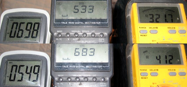
Here are the voltages that you get from the XPWR131. Top readings are "45 mode" and bottom is "300B mode". The yellow meter shows the resulting B+ voltage and the middle meter shows the HT taps that are currently powering it. The meter on the left is attached to the unused HT taps in that scenario.
Rknize, every respone i got from you and all the rest make me smile
I can't wait for a replay, like a child lol
1. I fill stupid to ask but what do you mean "You just tie-off..." tie-off what? To where? Which end?
2. Did you use the CXC125-10H-200mA DC choke? If no and i want do use it, how it'll effecet?
3. Can you please send me the parts list you used for your 300b TSE?
Many thanks to you all ! :-D
I can't wait for a replay, like a child
lol1. I fill stupid to ask but what do you mean "You just tie-off..." tie-off what? To where? Which end?
2. Did you use the CXC125-10H-200mA DC choke? If no and i want do use it, how it'll effecet?
3. Can you please send me the parts list you used for your 300b TSE?
Many thanks to you all ! :-D
Rknize,
About the 300b filaments-
"The 300B tube requires 5 volts and 1.2 amps for its filament. Some new production "300B tubes" require more filament current." a quote from tubelab.com. Even all the datasheets say that,
so why did you said
"TSE powers the 300B filaments with a regulated DC supply off of the 6.3V winding."
TNX.
ranhaber:
To tie-off the unused transformer taps, I just soldered them to an unused lug on a terminal strip so they don't touch anything. They are not used. If you use the XPWR131, you'll have a least one set of HV taps to tie off, as well as a filament center tap.
The 10H choke is an excellent choice, the DC resistance of the choke has an effect on your final B+ voltage. If you are curious about the B+, download Duncan Amps PSUDII and model it, it's very easy to use. You can adjust the B+ somewhat (if required) by the choice of the first cap in the PS. You just need to be close to your target voltages, tubes have a little wiggle-room as long as you do not exceed their max dissipation ratings.
The TSE uses the 6.3 volt tap to power the 5V regulator for the 5V (or 2.5V) filaments. The regulator requires some voltage "head room" to operate (ie if the supply voltage to the reg gets too close to 5V it cannot regulate properly). That's why the 6.3V tap is used. That extra voltage times current equals excess heat that needs to get dissipated in a heat sink.
Some 300B's use more current than others, so the ones that draw more current will run the regulator hotter. You'll want a good sized heat sink one the regulator; the cooler it runs the happier it'll be.
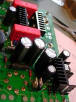
The regulator heat sinks are in the lower right corner of the picture. Bigger is better, in my build, the components are on the bottom of the PCB and I am a bit limited for space.
To tie-off the unused transformer taps, I just soldered them to an unused lug on a terminal strip so they don't touch anything. They are not used. If you use the XPWR131, you'll have a least one set of HV taps to tie off, as well as a filament center tap.
The 10H choke is an excellent choice, the DC resistance of the choke has an effect on your final B+ voltage. If you are curious about the B+, download Duncan Amps PSUDII and model it, it's very easy to use. You can adjust the B+ somewhat (if required) by the choice of the first cap in the PS. You just need to be close to your target voltages, tubes have a little wiggle-room as long as you do not exceed their max dissipation ratings.
The TSE uses the 6.3 volt tap to power the 5V regulator for the 5V (or 2.5V) filaments. The regulator requires some voltage "head room" to operate (ie if the supply voltage to the reg gets too close to 5V it cannot regulate properly). That's why the 6.3V tap is used. That extra voltage times current equals excess heat that needs to get dissipated in a heat sink.
Some 300B's use more current than others, so the ones that draw more current will run the regulator hotter. You'll want a good sized heat sink one the regulator; the cooler it runs the happier it'll be.
The regulator heat sinks are in the lower right corner of the picture. Bigger is better, in my build, the components are on the bottom of the PCB and I am a bit limited for space.
Attachments
Last edited:
1) Just cover the end of the wire with some electrical tape or heat shrink tubing and tuck it away somewhere. As boywonder said, you can also attach it to an unused terminal somewhere. In the end, they will not be part of the circuit.
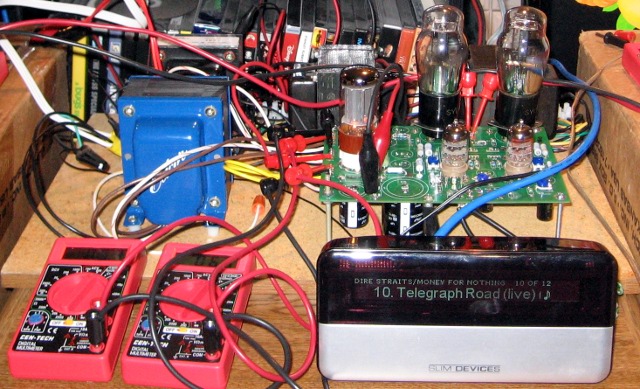
2) I used a Hammond 193J, IIRC, which has a 82 ohm DCR. Your's has a 75 ohm DCR. The DCR (DC resistance) of the choke has a part in the final B+ voltage of the filter. George's design specs a 150 ohm resistor if you are not using a choke. So a choke tends to make your B+ a little higher unless its DCR is 150 ohm. It just so happens that the Triad Magnetics C-14X has a 150 ohm DCR and is also quite cheap. A lot of people use the C-14X in SSE, TSE, and SPP builds. You can see the Hammond behind the Edcor XPWR131:
3) I will post it on my site when I get a chance and give you a link. I get asked for that a lot.
As for the output tube heaters, it's as boywonder said. George's design uses a linear regulator IC to supply a very quiet 5V to the 300B heaters (2.5V in the case of 45s). Such IC's have what's called a drop-out voltage, which is the lowest voltage between the IC's input and output under which it can operate. This particular IC has an unusually low drop out voltage, which works well in terms of efficiency. The heat sink that George specifies for this application had 45s in mind. 300Bs draw much more current, which causes the regulator to dissipate more heat. It will shut itself down if it overheats. Thus the need for a larger heat sink in most applications.
Last edited:
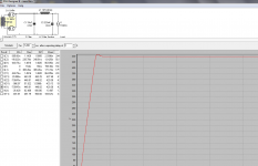
Ranhaber: Here is a basic PSUD model for your Tubelab SE power supply.
Once you have this circuit in PSUD, you can modify cap values, resistor values, choke values, etc. and see what B+ and ripple voltage you end up with. The smaller the ripple voltage, the better. However, you will find that it won't go to zero with practical capacitor values.
I modeled this with your proposed 360-0-360 transformer, and you can see that the B+ is around 440V, a little high.
Several assumptions were made here; the DC resistance of both the Edcor Transformer and choke are guesses. If the DCR for these parts is lower, the resulting B+ will be higher than shown....and higher DCR=lower B+
Here is a brief overview of setting up and using PSUDII:
Each stage/section of the schematic can be modified by right-clicking on that stage/section.
Each component value can be modified by right-clicking on the component.
Start by right-clicking on the transformer section and select vacuum tube full wave.
right-click on the capacitor section and insert an LC filter
right click on the 5K load section and change to constant current
Then right-click on individual components to change their values, and select V(I1) and click simulate to see the voltage at the constant current load.
The 164ma constant current load is (70ma x 2) for your 300B's + (12ma x 2) for the 5842's. I've neglected the current though the mosfet followers for simplicity. These results should get you in the ballpark.
You can reduce the value of the first cap to reduce B+. Below about 8uf or so the B+ will begin to drop.
Attachments
More questions:
1) If i'm puting small cap like 6uF and mesure the voltage, i get big osillations, allmost 490V, is it OK? if yes do i have to pick a cap with 500V?
2) If i'm going to put a motor run cap in parallel to C5, what is the recomended value for C5 and the motor cap? which type shell i buy?
3) One of George modification was ...
"My personal preference is to use a high quality electrolytic on the board, and connect an external (off board, mounted in the cabinet) paper in oil capacitor directly between the output transformer and the filament of the output tube."
connect the electrolytic cap to where? T2-2,T3-2 to ground?
Thanks
ranhaber:
Where are you putting the small 6uf cap? At C1 in PSUD (C4 on the TSE schematic)? At around this value (and lower uf) or so, it should start to decrease the B+ voltage. I'm not exactly following your first question........if your oscillations are 490V, you've got a model problem......
For C5, the bigger the better as far as ripple voltage goes, same with the motor run. IIRC, I'm running a 220uf Panasonic TS-HB or TS-UP electrolytic and a 100uf motor run. The 100uf motor run (paper/oil) cap is BIG.
George's comments pertain to locating the parallel motor run cap as close to the load as possible. Looking at the schematic, if you connect it to the top of the 10R resistor (R18/R29) and to the ground side of the filament, you are still in parallel with C5. Apparently, the 10R resistor won't affect this cap's operation if you tie one side of the cap to the bottom of the 10R resistor, which I think is what George is suggesting.
The idea here is that the motor run/PIO cap has very low ESR, and by having that close to the load it's able to provide the instantaneous current when needed for transients like bass drum whacks, etc.
BTW, paralleling 2 caps adds their capacitance, so if you are paralleling say a 220uf and a 100uf in PSUD, just make C2 320uf in the model.
As far as power supply cap voltage goes, multiply your transformer secondary by the square root of 2 (1.41) to get your max possible DC voltage. Most high voltage caps suitable for power supply use are typically rated for 50V higher than nominal voltage for short duration.
So for a 330V transformer 330V x 1.41=465 use 450 or 500V rated caps, and for a 360V rated transformer you'll definitely need 500V rated caps as the transient start-up voltage is can be as high as 507V.
For affordable high voltage low ESR caps look at panasonic TS-HB (450V), TS-UP (500V-getting hard to find in stock), and Cornell Dublier caps. There are also JJ brand HV (500V) caps, the same folks that make tubes. There are a fair number of other HV cap manufacturers as well.
Last edited:
1) Do you have a choke in your model?
3) The SSE PCB has terminals for an off-board capacitor, which most builders use to attach a film capacitor of some sort. The TSE PCB does not have these terminals, so you have to wire the off-board cap in yourself. That is the film cap George is talking about and it goes in parallel with C5. I also have a 220uF for C5 (as well as for C2 in my SSE), as it fits in the PCB perfectly. I don't think I have an off-board cap on my TSE right now, but the SSE has a 90uF motor run cap IIRC.
3) The SSE PCB has terminals for an off-board capacitor, which most builders use to attach a film capacitor of some sort. The TSE PCB does not have these terminals, so you have to wire the off-board cap in yourself. That is the film cap George is talking about and it goes in parallel with C5. I also have a 220uF for C5 (as well as for C2 in my SSE), as it fits in the PCB perfectly. I don't think I have an off-board cap on my TSE right now, but the SSE has a 90uF motor run cap IIRC.
Boywonder:
I see that if i put a low value, 6.8uf, i can lower the voltage to 400V but... I also see in PSUD that i get very big oscillations on c1V.
What can be my model problem?
Big oscillations at C1 are normal, as you are just beginning the filtering. I only look at the voltage at the constant current load(s).
As you add RC or LC stages, notice that the ripple voltage drops after each stage. Adding stages also increases output impedance. So, everything is a compromise.
Is the Edcor 10H/200ma choke DCR actually 75 ohm? I could not find the DCR value at Edcor's website. Do you know the secondary resistance of the power transformer from either end to the CT?
- Status
- This old topic is closed. If you want to reopen this topic, contact a moderator using the "Report Post" button.
- Home
- More Vendors...
- Tubelab
- Tubelab SE