Hi Guys,
Need your help to check if my Hammond Power Transformer 374BX used in Simple SE is still in good condition?
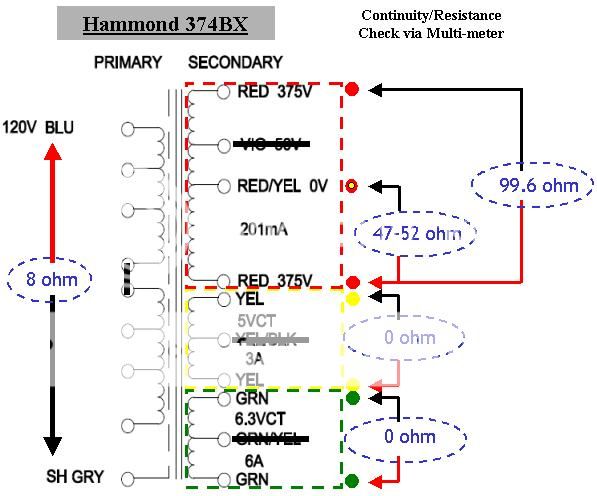
Reason for asking is because my last power up I heard a loud hum after a month of "hibernation". Upon power off, the 374Bx is very hot. Afraid that it might be dead/fried I had performed continuity/resistance measurement via a multimeter and the result as shown below. How I wish I do have another power transformer for the same comparison but is the 374BX still good/fit for use?
Appreciate any form of advice. TIA
Need your help to check if my Hammond Power Transformer 374BX used in Simple SE is still in good condition?
Reason for asking is because my last power up I heard a loud hum after a month of "hibernation". Upon power off, the 374Bx is very hot. Afraid that it might be dead/fried I had performed continuity/resistance measurement via a multimeter and the result as shown below. How I wish I do have another power transformer for the same comparison but is the 374BX still good/fit for use?
Appreciate any form of advice. TIA
Why not just disconnect all of the secondaries from the board and carefully check the voltage of each secondary with the transformer powered up?
The voltages should be a bit high since the transformer is completely unloaded, but that should answer your question.
The 5V rectifier and 6.3V heater windings can be difficult to measure since they are usually less than an ohm.
For reference, I just measured a 273BX (350-0-350 @ 175ma) and the B+ secondaries are 77R across the ends, and about 39R from either end to the CT. The 5V and 6.3V measure about .4R end to end.
Last edited:
Why not just disconnect all of the secondaries from the board and carefully check the voltage of each secondary with the transformer powered up?
Good idea, and leave it powered up for an hour or so. It should not get hot or buzz. Mildly warm is OK.
It is extremely rare for a transformer to die from sitting on the shelf. Electrolytic caps and rectifier tubes are far more likely to die from non use.
Had been housing the current wooden case SSE to Hammond Alu case all this while.
Done with the secondary measurement (WITHOUT load) and reading as follows:
Red-Red: 800V
Red-Red/Yel: 400V
Green-Green: 6.25V
Yel-Yel: 5.24V
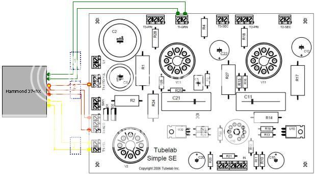
However, upon connecting to the SSE's PCB (tried all combination of setting be it 4/8ohm spk out, Triode/UL or with or without CFB), the 374BX hum (vibrate) and can be heard and feel. By just removing the Red-Red & Red-Yel wires (#2 from pic attached - No Load on High Tension) from the SSE's PCB no hum (vibrate) of the 374BX can be heard (feel).
Question:
Without load no hum (vibrate) with the above measure on the secondaries. But with load 374BX hum (vibrate) upon power ON. Is the 374BX defective and what else can I do?
Appreciate any kind of inputs and advices/suggestions.
Thanks
Done with the secondary measurement (WITHOUT load) and reading as follows:
Red-Red: 800V
Red-Red/Yel: 400V
Green-Green: 6.25V
Yel-Yel: 5.24V
However, upon connecting to the SSE's PCB (tried all combination of setting be it 4/8ohm spk out, Triode/UL or with or without CFB), the 374BX hum (vibrate) and can be heard and feel. By just removing the Red-Red & Red-Yel wires (#2 from pic attached - No Load on High Tension) from the SSE's PCB no hum (vibrate) of the 374BX can be heard (feel).
Question:
Without load no hum (vibrate) with the above measure on the secondaries. But with load 374BX hum (vibrate) upon power ON. Is the 374BX defective and what else can I do?
Appreciate any kind of inputs and advices/suggestions.
Thanks
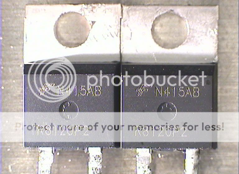
Is it possible that I had fried the FRED Diode (D1 & D2) that resulted in the shorted Red-Red wire of the 374BX resulting in Hum (vibrate).
I measure the continuity of the diode and was found that the diode body (k-cathode) was shorted to the anode as beep beep sound was heard. (no tubes inserted into any of the tube sockets).
I measure the continuity of the diode and was found that the diode body (k-cathode) was shorted to the anode as beep beep sound was heard. (no tubes inserted into any of the tube sockets).
Junior: What's your B+ voltage and heater voltages when all of the tubes are installed and a proper load is connected to the speaker terminals?
If any of your voltages are out of spec (low), that would indicate a short condition and would make the transformer hum. Are the screws clamping the end bells on the transformer tight?
If any of your voltages are out of spec (low), that would indicate a short condition and would make the transformer hum. Are the screws clamping the end bells on the transformer tight?
Is it possible that I had fried the FRED Diode (D1 & D2) that resulted in the shorted Red-Red wire of the 374BX resulting in Hum (vibrate).
Yes this has happened in the past. Remove the diodes, the amp will work fine without them. They are only needed when using the solid state rectifier option.
hi boywonder,
checked all the screw on the power transformer is all secured tightly.
i mounted it on top of an aluminium Hammond chasis.
Hi Geroge,
Desolder both D1 and D2 (both are ISL9R8120P2) and check via DMM.
D2 is "dead". replace both D1 & D2 with DSEI12-12A.
Hope I had nailed down to the culprit.
Will try it out tonite and report back.
replace both D1 & D2 with DSEI12-12A.
There have been issues with the IXYS parts ever since IXYS changed something about 3 years ago (probaly a process geometry change). I have been reccommending a Fairchild part that doesn't blow, ISL9R8120P2 It has been discussed in the Tubelab forum before.

anyway, let me try it out tonite and hope that the 12A (DSEI12-12A) version will hold.
Junior: It's not the current rating that is a problem. It's a voltage spike at turn-on from the power transformer, with the Hammond units being especially prone to this. Depending on where the AC mains waveform is when you hit the power switch, the transformer can send a voltage spike (sometimes in excess of 2KV) to the rectifiers, and the 1200V rated parts get toasted.
Tubelab has discussed this in a thread around here somewhere, having flipped the power switch over and over while looking at the diode voltage with a scope. So leaving them out altogether if you are running tube rectification will save you from future issues.
Hi boywonder,
Understand the part that George mention that I do not need the SS rectifier. But I had already drilled hole in the front panel for it.
Good New:
Finally, I manage to stop the humming (vibrating) from the Hammond 374BX after replacing D1 & D2. The fried D2 caused the short circuit on the high tension resulting in the humming.
Bad New:
Hooked up the SSE, No output. I mean no music.
Please suggest where can i start to determine the cause.
For the time being, I will be looking at all my wiring all over again.
Thanks
Junior: It's not the current rating that is a problem. It's a voltage spike at turn-on from the power transformer, with the Hammond units being especially prone to this.
Actually the voltage spike occurs at turn off. If turn off happens when the current through the transformer secondary is at a peak, it will try to continue causing a voltage spike in excess of 2 KV. This has been known to blow diodes, and even 5AR4's. You don't know the rectifier has failed until the next turn on. The exact mechanism for failure is an avalanche breakdown in the SS diode. The diode conducts in the reverse direction trying to clamp the spike in a manner similar to a zener diode. The IXYS parts are not rated for avalanche energy, while the Fairchild parts are. This is the first I have heard of a Fairchild part blowing.
Hooked up the SSE, No output. I mean no music.
Start with basic voltmeter checks. With the negative voltmeter lead on ground, check the plate voltages on the output tubes. It should be over 400 volts. Look for 35 to 45 volts on the cathodes. Check for about 175 volts on the 12AT7 plates.
Hi George,
Thanks for the quick reply.
I will perform the measurement tonight.
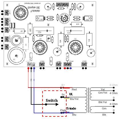
Let me share with you my wiring for UL/Triode Select and Able/Disable Feedback & Spk Ohm Select implementation:
UL or Triode Select
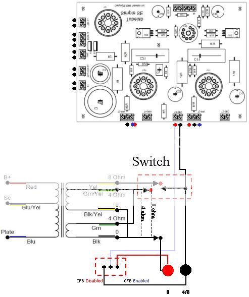
Able/Disable Feedback & Spk Ohm Select
The output transformer secondaries' was connected in reverse and is it applicable to Hammond 1629SE OPT that I am using?
Thanks for the quick reply.
I will perform the measurement tonight.
Let me share with you my wiring for UL/Triode Select and Able/Disable Feedback & Spk Ohm Select implementation:
UL or Triode Select
Able/Disable Feedback & Spk Ohm Select
The output transformer secondaries' was connected in reverse and is it applicable to Hammond 1629SE OPT that I am using?
Hi George,
Power up the SSE with all tubes in. It glows nicely with no anomaly.
I check the supply voltages from the power transformer on the connectors on the SSE PCB. All reading is good at: 5.28VAC, 6,28VAC & 785VAC.
I measured the voltage across the output tubes and 12AT7 as suggested and I get near to 0V (both AV and DC setting). The only sensible reading I get is the heater AC voltage.
Please advice what can I do next. Thanks
Hi George,
Power up the SSE with all tubes in. It glows nicely with no anomaly.
I check the supply voltages from the power transformer on the connectors on the SSE PCB. All reading is good at: 5.28VAC, 6,28VAC & 785VAC.
I measured the voltage across the output tubes and 12AT7 as suggested and I get near to 0V (both AV and DC setting). The only sensible reading I get is the heater AC voltage.
Please advice what can I do next. Thanks
After days and weeks of struggling, blowing fuse and diode, I had finally got to the root of the problem.
Recall the fired FRED. Tt had caused the discontinuity in the plated thru' hole (D2 Anode) and that why I did not have any VAC reading between the plates for the 5AR4.
Currently, I had the SSE wired with NO FEEDBACK and in TRIODE mode.
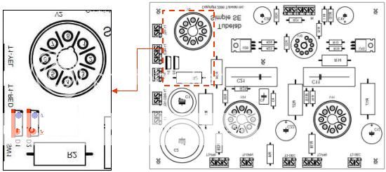
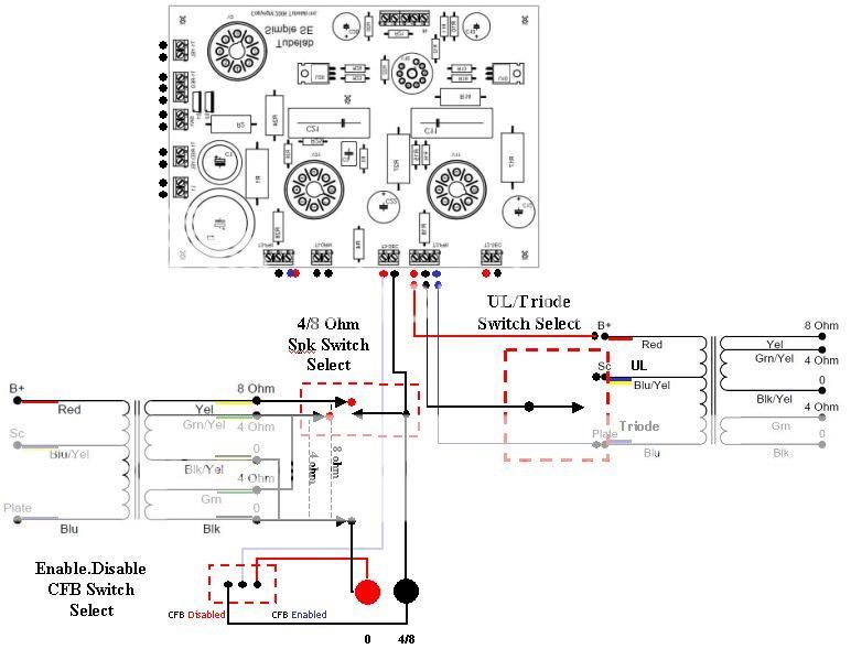
I wish to had it wired to be selectable for:
1) Able/Disable Feedback Select,
2) UL/Triode mode Select and
3) 4ohm/8ohm Spk Out Select.
The below diagram are my wiring implementation and please help me check if there is any error. Thanks in advance
After days and weeks of struggling, blowing fuse and diode, I had finally got to the root of the problem.
Recall the fired FRED. Tt had caused the discontinuity in the plated thru' hole (D2 Anode) and that why I did not have any VAC reading between the plates for the 5AR4.
Currently, I had the SSE wired with NO FEEDBACK and in TRIODE mode.
I wish to had it wired to be selectable for:
1) Able/Disable Feedback Select,
2) UL/Triode mode Select and
3) 4ohm/8ohm Spk Out Select.
The below diagram are my wiring implementation and please help me check if there is any error. Thanks in advance
Finally, I manage to solve all the problems that I had encountered.
Now my Tubelab Simple SE is singing again.
Thanks to all who help in one or another way.
- Status
- This old topic is closed. If you want to reopen this topic, contact a moderator using the "Report Post" button.
- Home
- More Vendors...
- Tubelab
- Hammond Pwr Trans 374BX Diagnosis