I bought 2 of these, with 1 in my SSE; they behave electrically just as 5AR4s.
5AR4 Rectifier Tube Mil Philips Mislabeled 5V4GA | eBay
Also, Eli Duttman posted this schematic for new production 5AR4s for keeping them alive
The updated SSE pcb's now include this - D3, D4 and TR1
on the new boards where thermisitor cl-140 goes I was going to substitute a cl-90 since I have one. For some reason these holes are smaller and the cl-90 will not fit. I would like to avoid any more shipping fees if possible thoughts?
The leads on the cl-140 will be the same thickness. You can clip two pieces
from the leads of a spare resistor or other similar wire and solder them on
to the leads of the thermistor. You should probably shorten the leads of the
thermistor before soldering the pieces.
on the new boards where thermisitor cl-140 goes I was going to substitute a cl-90 since I have one. For some reason these holes are smaller and the cl-90 will not fit. I would like to avoid any more shipping fees if possible thoughts?
The CL-90 is a higher-current part, so the leads are larger. Personally, I would mount it off-board rather then try to shove it into the PCB. It would go in series between the center tap of the HT winding and the PCB. It's not the ideal rating for this position, though, because it will not get not enough. It is better off in series with the entire amp. That said, I had a CL-90 in this position originally and I coped with the problem by wrapping the part in heat shrink tubing to let it get up to temp.
Last edited:
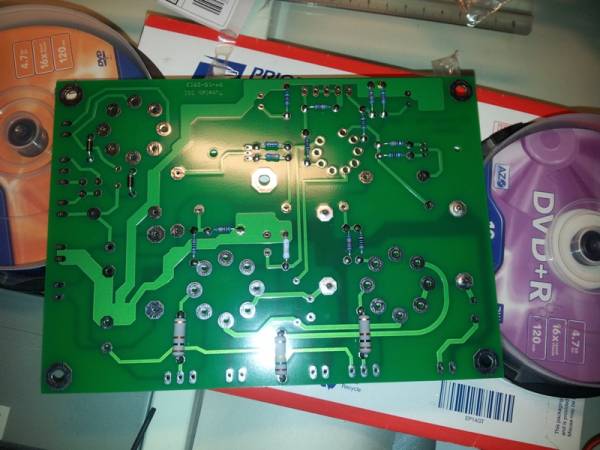
Here are some pictures of my build. I just soldered tube socket and R17/R27 on the top side. Everything else is on bottom side. I've a design in mind, but I will ask some questions about the feasibility...
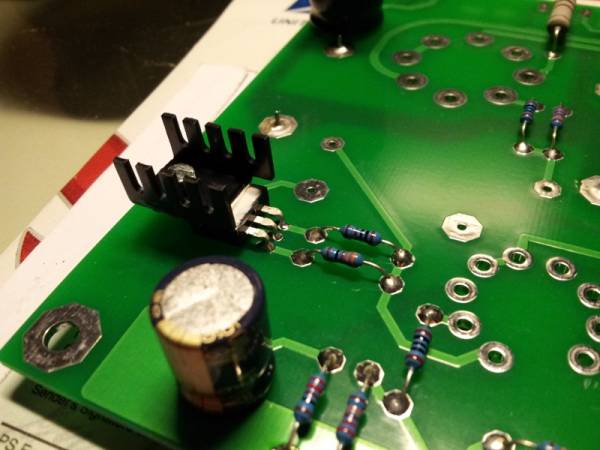
After having soldered resistors :
Binding posts used for R17 and R27 :
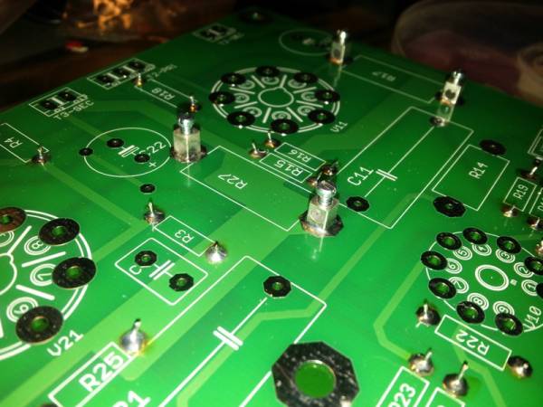
I have thermal paste from a previous project, so I added it :
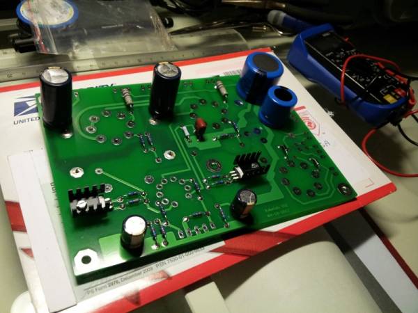
And a global view :
I soldered tube socket and connectors yesterday, pictures to be done...
After having soldered resistors :
Binding posts used for R17 and R27 :
I have thermal paste from a previous project, so I added it :
And a global view :
I soldered tube socket and connectors yesterday, pictures to be done...
I have only recently received my SSE board and note that I have the 3 additional component positions. Thank goodness for this oldish thread. It certainly helped to clear up the mystery of the additional components....well almost.
I assume that D1 and D2 remain as set out in the parts page.
It seems also that D1- 4 are all designed to assist the rectifier tube and are connected to and are active with the tube. Does this remove the option to switch between solid state and tube rectification?
The additions and substitutions do become a bit confusing. I have these on order
Fairchild RHRP15120 (D1 and D2)
DIODES INC. 1N4007-T ( D3 and D4)
IXCP10M45S (U10 and U20)
Have I got these right?
Thanks
Thanks zman, much appreciated.
I'm still a bit confused over the rectification, though. I do plan to use tube rectification , but to have solid state as an switchable option. All through the tubelab web pages SS is indicated as optional, either/or. But there quite a lot of posts in other threads here which suggest both are used together i.e. the ss supporting or protecting the tube. Certainly looking at the traces on the pcb they seem to suggest this is so.
If this is so, that's fine: I won't bother with an extra switch.
Last edited:
exwiso,
IMHO better to stick with tube rectification only - the (longer) warm up time of the 5AR4 rectifier tube specified by George results in the other tubes getting the full B+ a bit later, which is good for the life of the tubes.
My understanding from George's post on the first page of this thread is that the D2 and D3 are to keep the rectifier safer.
If I may ask, what are the other component choices you have made e.g. power transformer, OPTs, choke, tubes?
Pretty orthodox in the power side; Hammond 374BX with James 6123 OPT's and the Triad F-14X choke.
I have been thinking about the Mundorf tubecaps instead of the electrolytics though. They do a 47uFat 600v but only 100uF or 200uF, both at 550v. I had been thinking of using the 200uF in C2.
I would be interested in any opinions on this?
I have been thinking about the Mundorf tubecaps instead of the electrolytics though. They do a 47uFat 600v but only 100uF or 200uF, both at 550v. I had been thinking of using the 200uF in C2.
I would be interested in any opinions on this?
exwiso,
IMHO better to stick with tube rectification only - the (longer) warm up time of the 5AR4 rectifier tube specified by George results in the other tubes getting the full B+ a bit later, which is good for the life of the tubes.
My understanding from George's post on the first page of this thread is that the D2 and D3 are to keep the rectifier safer.
Just to clarify, use the rectifier + D2, D3, but no switch.
")
- Status
- This old topic is closed. If you want to reopen this topic, contact a moderator using the "Report Post" button.
- Home
- More Vendors...
- Tubelab
- Starting a SSE build