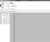
Here is a rough PSUDII model.......
To see what the B+ will be with other rectifiers, bias current, cathode R's etc. download and install PSUDII from:
PSUD2
Then left click or right click on the schematic in PSUDII to change values and mimic what I've posted here; it's really easy. Important note-You can click on the various components to change, or on each stage "block" to change.......
Then select whatever parameter that you want to sim (voltage across the current load) and click the simulate button.
The model above assumes about 50ma per output tube and 20ma for the 12AT7 (wild-*** guess) for a total of 120ma.....your bias current is simply the voltage drop across the cathode R divided by the cathode R value (Ohm's law). Multiply by 2 (2 output tubes) and add the current for the 12AT7.
The transformer resistance has a fairly large impact on the B+ voltage waveform and overshoot; I guessed at 100 ohms....if you use less the B+ goes higher and overshoots. You can always de-solder and measure the resistance across the transformer secondaries and use that value in PSUDII. Clicking the transformer properties box and inputting additional values will allow a bit more fine tuning of the model.
Attachments
You can always de-solder and measure the resistance across the transformer secondaries
If you didn't install the SS diodes, there is no need to unsolder anything. A cold rectifier tube doesn't conduct but you could unplug it if you want. My amp uses the same Allied transformer aid I measure 63 ohms per side, 126 ohms total. I couldn't fit a real choke in my amp so I stuffed a little 1 Hy unit under the deck. It measures 54 ohms.
20ma for the 12AT7 (wild-*** guess)
The design target was 8 mA per section but every CCS is different. It should be between 6 and 10 mA per section. I have been using 20 for my guesses too. I have been cranking my KT88's to 100 mA each. The Allied gets too hot to touch, but hasn't fried yet.
I never made it to the warehouse last weekend to fetch my big box of 6L6's. MAybe this weekend.
If you didn't install the SS diodes, there is no need to unsolder anything. A cold rectifier tube doesn't conduct but you could unplug it if you want. My amp uses the same Allied transformer aid I measure 63 ohms per side, 126 ohms total. I couldn't fit a real choke in my amp so I stuffed a little 1 Hy unit under the deck. It measures 54 ohms.
The design target was 8 mA per section but every CCS is different. It should be between 6 and 10 mA per section. I have been using 20 for my guesses too. I have been cranking my KT88's to 100 mA each. The Allied gets too hot to touch, but hasn't fried yet.
I never made it to the warehouse last weekend to fetch my big box of 6L6's. MAybe this weekend.
How hot have you biased el 34's in there? I just set mine up with allied pt and 3k opt's with 560 ohm cathode resistor. It is PERFECT with 6l6gc's, but I haven't had the courage to try the 34's yet. If I have to I can drop the 5ar4 to a 5u4.
How hot have you biased el 34's in there?
When I first built the amp (and its brothers) I used 560 ohm resistors. I could swap between 6L6GC, EL34 and KT88 with no changes. As my line voltages crept up over the years the 6L6GC's began to glow first. I think a 620 ohm might be a better choice for a universal amp today. I have found that a GOOD EL34 can be plugged right into this amp. Not all EL34's were assembled with care and treated gently all the way to your amp. The result is a slight missalignment in the grid rods and grid wires leading to uneven current distribution inside the tube. This is a problem with any tube, but I seem to have the worse luck with new production EL34's.
Try your EL34's (and your current 6L6's). Turn off all the lights in the room. Examine the plate structure for any dim red spots anywhere on the plates. Look through all of the holes in the plates (EL34 and KT88). You should see the vertical cathode rod glowing red. There MUST be no glow on any of the grid wires (horizontal). A glowing plate will kill the tube slowly since it is releasing trapped impurities into the vacuum (outgassing). A glowing grid wire will kill the tube fairly quickly since it will sag causing further misalignment, and more heating. it will eventually touch another grid causing really bad stuff.
Just put two new production tubes through pressure cooker. I used the Valve Art 350b with 3k opt, 235v on plate,5ar4, and 560 ohm resistor for two hours and it sounded great. No hot spots at all. I did the same with the tung-sol 6l6g and one plate was glowing with a red stripe in about ten minutes. With a 5u4 it sounded better and no glow.
Guessing it was a twenty volt drop or so with 5u4. FWIW.
Guessing it was a twenty volt drop or so with 5u4. FWIW.
valve art 350b
I've been pounding these tubes for a couple days. I really like the way they sound.I can't find a data sheet for the new production, but I have been feeding them 440v with 560 cathobe resistor into 3k opt. No problems. Wide spacious sound, very good bass and vocals. Cheap to try.
I've been pounding these tubes for a couple days. I really like the way they sound.I can't find a data sheet for the new production, but I have been feeding them 440v with 560 cathobe resistor into 3k opt. No problems. Wide spacious sound, very good bass and vocals. Cheap to try.
Don't know if anybody is still reading this, but I abused some more tubes yesterday. Went with the EH6ca7's, 440 B+, 560 cathode resistor, 3k opts. Boy did they sound good. Only problem is the grids started to glow in several places after a short amount of time. Tried them again today with 5u4(less voltage) and they crackled as they warmed up so I took them out. I don't think they are very tough tubes.
I've just learned about the Valve-art 350B's like few days ago. It's time I got new tubes for my amp. Looking at the Western Electric datasheet..it seems like we need some minor adjustments. Bias is only 50 mA and filament current draw is 1.6 Amp vs. just 0.9 for 6L6GC. I have 720 ohms resistor to keep bias happy but how to tweak the filament current draw? I'm using the Edcor XPWR0035. HV secondary has 2 amps available.
http://www.tubezone.net/pdf/we350b.pdf
http://www.tubezone.net/pdf/we350b.pdf
Last edited:
I've just learned about the Valve-art 350B's like few days ago. It's time I got new tubes for my amp. Looking at the Western Electric datasheet..it seems like we need some minor adjustments. Bias is only 50 mA and filament current draw is 1.6 Amp vs. just 0.9 for 6L6GC. I have 720 ohms resistor to keep bias happy but how to tweak the filament current draw? I'm using the Edcor XPWR0035. HV secondary has 2 amps available.
http://www.tubezone.net/pdf/we350b.pdf
I can run the valve art 350b tubes all day long with 440v B+ and the 560 ohm resistors. In ul with feedback. They sound good and the plates don't glow. I don't think they are like the originals.
I can run the valve art 350b tubes all day long with 440v B+ and the 560 ohm resistors. In ul with feedback. They sound good and the plates don't glow. I don't think they are like the originals.
Valve art supposedly sources from Shuguang. Shuguang 6L6G is only rated at 400V and 25 W plate dissipation. I guess Valve art 350B's have MUCH higher plate dissipation than that.
Been busy digging for 350B datasheet. And found 350C datasheet. "C" stands for carbon so basically the same tube but with carbon plate. Plate voltage is 400V. So I guess using it with B+ of over 400V is not a good idea?
http://www.tubeampdoctor.com/images/File/350C.pdf
Also, since this tube draws 1.6 amps...is it going to be problem if The rectifier tap only has 2 amps? Kkcinc, Which transformer you are using?
http://www.tubeampdoctor.com/images/File/350C.pdf
Also, since this tube draws 1.6 amps...is it going to be problem if The rectifier tap only has 2 amps? Kkcinc, Which transformer you are using?
Last edited:
Also, since this tube draws 1.6 amps...is it going to be problem if The rectifier tap only has 2 amps?
No, the output tubes run from the 6.3 volt winding which has nothing to do with the rectifier. As long as the total draw for all the tubes EXCEPT the rectifier (which has its own winding) add up to less that the rating of the 6.3 volt winding, you are OK in this regard.
The plate voltage is the voltage measured from the cathode of the tube to the plate of the tube. The B+ is the total voltage supplied by the amps power supply. Some of the B+ is lost in the OPT, and some is dropped in the cathode resistor. The usual loss in these two is 30 to 40 volts so you will be very close to the 400 volt rating. Most tubes have plenty of margin in this regard, but I have no experience with the 350B.
- Status
- This old topic is closed. If you want to reopen this topic, contact a moderator using the "Report Post" button.
- Home
- More Vendors...
- Tubelab
- Simple SE 6l6 tube types