Given that the resistor is bypassed by a huge cap, I am a bit skeptical that the cathode resistor design can make an audible difference here unless something else was awry.
Not only does it make a difference, it is a rather large night-and-day type difference.
It's a small price to pay given the quality you are getting for the price of their OPTs. I was so pumped when I found out about these guys from this forum, especially how they can so easily make custom power transformer designs and are willing do to so for the DIYer. No more scrolling back and forth through Hammond's website trying to find a workable solution only to have it overheat and be way out of spec in the end.
For the switch, it doesn't have to be double-deck. It just needs to have two poles. For 6 or fewer positions, they can fit two poles on one deck. Just FYI if you are searching on Mouser or wherever. Mine is 2P6T single deck:
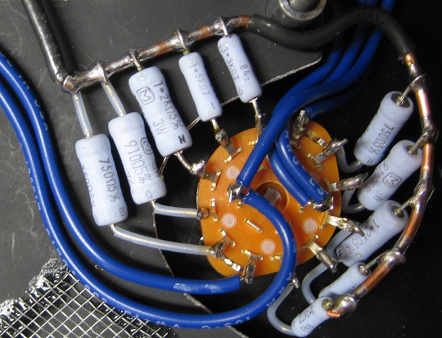
If I get this picture correctly all the resistors are connected a common wire
that goes to the ground connection of R17 and R27 then the the wires from
the two center pins one each go to the live connection of R17 and R27 is
this correct ?
The additional wires connected to the center pins and the two outer pins
where do they go ?
Last edited:
There are 4 other resistors that are not pictured here. They are 680 ohm, 5W types in the big, rectangular package (same Yageo SQP series that George specs in the parts list). They are mounted in a piece of aluminum u-channel that acts as a heat sink to the chassis. There are two used for each channel. One is permanently connected to the PCB in the R17/27 position. The other is in parallel, with one of the leads connecting here. So with the switch rotated in the fully CW position, I have two 680 ohm power resistors in parallel, for 340 ohms.
There are 4 other resistors that are not pictured here. They are 680 ohm, 5W types in the big, rectangular package (same Yageo SQP series that George specs in the parts list). They are mounted in a piece of aluminum u-channel that acts as a heat sink to the chassis. There are two used for each channel. One is permanently connected to the PCB in the R17/27 position. The other is in parallel, with one of the leads connecting here. So with the switch rotated in the fully CW position, I have two 680 ohm power resistors in parallel, for 340 ohms.
Is this why you connected them separately from the other resistors ?
Do they generate a lot of heat when paralleled for 340 ohms ?
- Status
- This old topic is closed. If you want to reopen this topic, contact a moderator using the "Report Post" button.