Has anyone tried (or have any advice) regarding selection of R17/R27 for the cathode to ground resistors?
The parts listing and docs refer to using 560 ohm, 5W, 20% tolerance units.
Is there any reason that something like a linear pot (e.g. Alpha part no. VW24F-10-19.5K-B2K 2kOhm full sweep) would be a bad choice?
It is inexpensive, provides the 5 watt power rating, is also plus/minus 20% tolerance, would allow adjustment (while the amp is OFF, of course) to dial in the resistance to suit your specific B+, etc.
At $5 per unit, this seems like a fair trade-off. I must be missing something here, yes?
Brad
Well, you'll need slightly different resistor values depending on what output tubes you are planning to run.
Several folks here have wired up a several values with a selector switch or jumpers to use when changing to different output tubes.
A pot that goes to zero ohms may not be a good idea since you can potentially red plate (melt) your output tubes if you make a mistake. Perhaps a pot in series with the lowest value R you need......or in parallel; that'll require a little ohm's law. You'll also want to have both channels fairly well matched....
If you think about it, you probably only need say 3 values to cover most tubes commonly used in the amp.
Well, you'll need slightly different resistor values depending on what output tubes you are planning to run.
Several folks here have wired up a several values with a selector switch or jumpers to use when changing to different output tubes.
A pot that goes to zero ohms may not be a good idea since you can potentially red plate (melt) your output tubes if you make a mistake. Perhaps a pot in series with the lowest value R you need......or in parallel; that'll require a little ohm's law. You'll also want to have both channels fairly well matched....
If you think about it, you probably only need say 3 values to cover most tubes commonly used in the amp.
I have noticed the selector switch option in scanning the TubeLab board.
The idea of a series value to set a minimum is a good one, or some R1*R2/(R1+R2) math to achieve something similar. That would at least avoid the Flying Wallendas family pyramid without a net scenario and avoid a core meltdown.
I would prefer to minimize the number of times I have to "get under the hood", so to speak, simply to change output tubes to something needing more/less current on the cathode.
Boywonder, consider your "minimum resistance idea" adopted.
Cheers,
Brad
provides the 5 watt power rating,
A 5 watt pot is only 5 watts if you are using the entire resistance. If you use 1/4 of the 2K pot to get 500 ohms you only have a 1.25 watt pot and it won't live long. I tried it and I fried it! It was totally unstable before it fried too.
The most reliable solution is a switch and a few resistors. Put a 1K or an 820 ohm in the board and use a switch to add resistors in parallel to get the desired value.
Really want the adjustability of a pot? Here is how to do it.
Put the 1K resistor in the board. Wire a 1K resistor and your 2K pot in series, then put the series pair in parallel with the 1K that is on the board.
With the pot all the way down you have two 1K resistors in parallel for 500 ohms. This will work with stout (EH) KT88's and will over dissipate the smaller tubes but not subject them to instant death like a single pot set to 0 ohms.
With the pot all the way up you have 3K ohms in parallel with the 1K on the board for 750 ohms.
So that's the reason...A 5 watt pot is only 5 watts if you are using the entire resistance.
Really want the adjustability of a pot? Here is how to do it. Put the 1K resistor in the board. Wire a 1K resistor and your 2K pot in series, then put the series pair in parallel with the 1K that is on the board.
With the pot all the way down you have two 1K resistors in parallel for 500 ohms. This will work with stout (EH) KT88's and will over dissipate the smaller tubes but not subject them to instant death like a single pot set to 0 ohms.
With the pot all the way up you have 3K ohms in parallel with the 1K on the board for 750 ohms.
This could be an option. RKnize's message just above this reply is valuable too. From his webpage, I noticed that he made a selector switch with multiple values, along the lines of what BoyWonder (above a bit) suggested.
Since I am not too sure of what my power supply output voltage will be, I was hunting for a solution of the cathode resistance challenge so I could tweak the tube dissipation to suit my specific situation.
So, effectively, my conclusion would be:
1) ENSURE you have a minimum resistance between the output tube cathodes and ground to prevent burning up a tube -- say 500 ohm or so (select to suit conditions...I understand from the "Tubes and Transformers" section of the TubeLabs page that one might select a lower initial value based on B+ voltage and desired tube dissipation.
2) If a Pot is used, it's handling capability is proportional to where in the Pot's sweep you are -- be aware of premature failure in considering such a device.
3) If a Pot is used, parallel it with a 5W resistor that establishes a minimum value (e.g. 1k ohms).
4) Place a minimum value on the board itself in the R17 and R27 positions.
Thanks for the support...I am looking forward to starting the build when my board arrives...hopefully early next week.
Since I am not too sure of what my power supply output voltage will be......
Unless you are way out of spec, tubes are tolerant of B+ voltage and current, as long as you are under the max dissipation ratings. Some will run comfortably over the max dissipation spec, as Tubelab George can certainly attest to....
If you are implementing a CLC power supply, you can reduce the value of the first cap to fine tune the B+ voltage a bit. Play with this in your PSUD model. You usually have to get below 10uf or less to see the B+ voltage start to drop.
Good suggestions. I am doin' the CLC power supply, leaning toward an Edcor XPWR002-120 power transfo.
Specs are 120VAC mains, 720 VCT @ 220mA, 6.3V @ 7A and 5V @4A. There's also a 60V bias tap 800mA capacity, but I won't use it. Selection was based on meeting TubeLab minimum specs, but also to have more 6.3V and 5V filament current, should I consider some later experiments with different rectifier, input stage and output stage tubes that have higher filament power requirements.
At $57.33 cost, this transfo looks like a savings of $20+ and meets all minimum Tubelab Specs. The cost of the XPWR035 and 059 are much higher from what I'm seeing at Edcor online.
The PSUDII model shows a B+ range from about 380-430 volts, depending on secondary winding resistance values, C1, C2, Cauxiliary and L1.
Since these are just models and I don't know what the final B+ will be, I wanted to come up with a relatively simple R17/R27 adjustment scheme to get an optimal Pdiss for the output tubes to save their lives for music playback, rather than a very short fireworks show if I calc'd the B+ and Pdiss wrong.
RKnize's scheme of a rotary switch to create a stepped resistance system looks like the way to go and incorporates your warning about avoid dangerously low R17/R27 conditions and those of the SimpleSE designer, TubeLab George.
I think I'm settled on a scheme now for safety and flexibility that will incorporate the ideas and warnings mentioned in this thread. My build should start shortly (board arrival soon, followed by BOM purchases)...so stay tuned.
Thanks to BoyWonder, RKnize and, or course, TubeLab George for the support.
Brad (aka Squiffiness)
Squiffi: Keep in mind that overspecing the transformer current rating for heaters (or any winding for that matter) means that you may be fighting excess voltage. For the heaters, you can use some series low R resistors to drop a little voltage if needed.
The Edcor units are a great value, and tend to be closer to Spec (and built a bit better) than Hammonds. Edcor has recently added chokes to it's lineup as well, now if they would just lose the blue color.......
The Edcor units are a great value, and tend to be closer to Spec (and built a bit better) than Hammonds. Edcor has recently added chokes to it's lineup as well, now if they would just lose the blue color.......
BoyWonder,Squiffi: Keep in mind that overspecing the transformer current rating for heaters (or any winding for that matter) means that you may be fighting excess voltage. For the heaters, you can use some series low R resistors to drop a little voltage if needed.
The Edcor units are a great value, and tend to be closer to Spec (and built a bit better) than Hammonds. Edcor has recently added chokes to it's lineup as well, now if they would just lose the blue color.......
I'll certainly be mindful of that if I go with the XPWR002-120.
BTW -- I did note that Edcor shows plain, unpainted end bell housings on their e-storefront.
I have been back and forth with Brian Watson at Edcor in the last couple of weeks on questions related to the Edcor lineup. Maybe I will ask him that since Edcor states that all product is "custom built to order" as orders roll in, whether they can build a roster of equipment without painting them the electric blue.
I will reply back via this thread with the Edcor reply.
Brad
Well, many of us here have asked.......but with Edcor you can have any color you want as long as it's blue......
I have purchased the bare endbells from them; they are cheap $$ and work fine although you still need to paint or powdercoat them. I've bought some of these endbells to retrofit onto 200 series Hammand transformers, they bolted right up. BTW, the blue powder coating can be removed with paint stripper.
Edcor used to have a $20 NRE fee for custom orders, but IIRC it's now $40. The customs end up as std product once someone orders and pays the NRE. The XPWR-131 is an example, Rknize ordered it custom for use in the Tubelab SE with 45's or 300B tubes and many of us have since purchased it stock off of the Edcor site.
The transformers are built to order, so that equates to a 5 week lead time typically, sometimes a little more or less. So placing your order sooner rather than later makes sense. I once asked Phyllis at Edcor why they don't stock popular transformers and she laughed, stating that they can barely keep up with the orders.
Last edited:
Well, many of us here have asked.......but with Edcor you can have any color you want as long as it's blue......
When did Edcor go "all Ford Model T" on their customers? Guess Henry Ford would be proud, but, of course he liked all the colours mixed together into black.
I have emailed Edcor support, just in case they had a good holiday and are feeling something other than festive gentian blue. Maybe neon green...or Addams Family midnight flat black. Suppose I could always get some rectangular covers like those from K&K, Lundahl or "Cubes for Tubes" in Denmark.
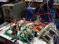
I have a pair of very early vintage Edcor OPT's. Back then they were only one color, bright METALLIC blue. It was the same color as a "Pimp my Ride" Cadillac that used to hang out in the neighborhood.
They can be seen in this photo, and yes that is a working amp.
They can be seen in this photo, and yes that is a working amp.
Attachments
It's just one of their little things...part of their trademark/identity I guess. The powder coating is tough to remove so I would pickup the raw bells that they offer if you find it offensive. Also, their core sizes are fairly standard. For example, the bells from a 193J Hammond choke fit one of my Edcor trannys perfectly.
That IS a shocking blue...I have a pair of very early vintage Edcor OPT's. Back then they were only one color, bright METALLIC blue. It was the same color as a "Pimp my Ride" Cadillac that used to hang out in the neighborhood.
Someone at Edcor must love gentian blue is all I can figure...It's just one of their little things...
Suprise of surprises...Edcor said 'no'. However, they did say "I'm sorry..." Guess I'll either learn to like Edcor Blue or get some covers or build a really deep chassis to hide them away. I really want to showcase the tubes, not so much the iron.I have emailed Edcor support, just in case they had a good holiday and are feeling something other than festive gentian blue
On the R17/R27 front, staying on topic, the selector switch (double deck, 1 pole per deck) is the way to go after some thought.
The scheme incorporates the advice in this thread, with a main "protective" R17/R27 soldered onto the SimpleSE board (e.g. the stock 560R). In parallel with each is then a 1k unit in series to the input of the selector, followed by a variety of stock values at the switch positions.
Maybe I could use all the convective and radiative heat from this resistor selector to cook off the Edcor Blue...hmmm.
It's a small price to pay given the quality you are getting for the price of their OPTs. I was so pumped when I found out about these guys from this forum, especially how they can so easily make custom power transformer designs and are willing do to so for the DIYer. No more scrolling back and forth through Hammond's website trying to find a workable solution only to have it overheat and be way out of spec in the end.
For the switch, it doesn't have to be double-deck. It just needs to have two poles. For 6 or fewer positions, they can fit two poles on one deck. Just FYI if you are searching on Mouser or wherever. Mine is 2P6T single deck:
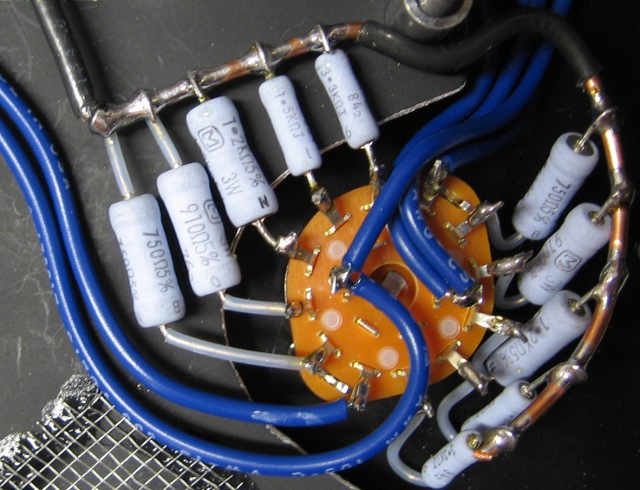
For the switch, it doesn't have to be double-deck. It just needs to have two poles. For 6 or fewer positions, they can fit two poles on one deck. Just FYI if you are searching on Mouser or wherever. Mine is 2P6T single deck:
It's a small price to pay given the quality you are getting for the price of their OPTs. I was so pumped when I found out about these guys from this forum, especially how they can so easily make custom power transformer designs and are willing do to so for the DIYer. No more scrolling back and forth through Hammond's website trying to find a workable solution only to have it overheat and be way out of spec in the end.
For the switch, it doesn't have to be double-deck. It just needs to have two poles. For 6 or fewer positions, they can fit two poles on one deck. Just FYI if you are searching on Mouser or wherever. Mine is 2P6T single deck:
Is this a a suitable switch for this purpose ?
Ebay-rotary-selector-switch
The type of resistor makes a pretty big difference. I started with Kiwame (Carbon Film) due to a friend's recommendation and later changed out my cathode resistors to Mills non-inductive wirewound. Mills is far superior IMO and I'd never use Kiwame again unless you want a warm (distorted) sound.
- Status
- This old topic is closed. If you want to reopen this topic, contact a moderator using the "Report Post" button.
- Home
- More Vendors...
- Tubelab
- SimpleSE R17_R27 selection