Dear All,
I was playing with a new scope I have, measuring the TubelabSE 45 I have in the office. Here are my findings, and I was wondering if this behavior is normal, or there is something wrong.
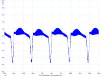
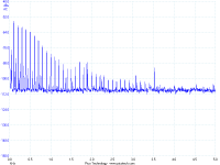
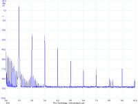
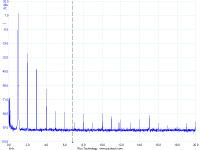
The first and the second pictures show the output with input shorted.
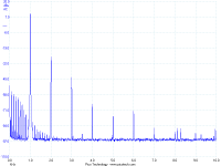
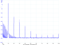
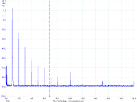
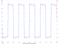
The third and fourth are the output with a test signal.
As I did some tube rolling to check if there could be a problem with one or more tube, the last picture is what I found with a lousy input tube.
Now my question is: is the shape of the noise floor normal, or there is something wrong ? I tried to change rectifier, but no change.
The amp was always a bit noisy, but with the DMM I was measuring 3mV of ripple at the output, so I thought that the noise was evident for the efficient speaker and for the fact that I sit very close to them. But now I think that the noise could be so audible because it is at higher frequency then the expected 100 Hz.
D.
I was playing with a new scope I have, measuring the TubelabSE 45 I have in the office. Here are my findings, and I was wondering if this behavior is normal, or there is something wrong.
The first and the second pictures show the output with input shorted.
The third and fourth are the output with a test signal.
As I did some tube rolling to check if there could be a problem with one or more tube, the last picture is what I found with a lousy input tube.
Now my question is: is the shape of the noise floor normal, or there is something wrong ? I tried to change rectifier, but no change.
The amp was always a bit noisy, but with the DMM I was measuring 3mV of ripple at the output, so I thought that the noise was evident for the efficient speaker and for the fact that I sit very close to them. But now I think that the noise could be so audible because it is at higher frequency then the expected 100 Hz.
D.
Attachments
I did.
Here's FFT analyzer of my TSE at 1W 8 Ohm load.
I don't notice much of noise floor issue. It shows 1 mV at the speaker terminal when I put voltmeter across.
Question: Dose the quality of input tube make harmonic distortions stretch out that far in your case?
Here's FFT analyzer of my TSE at 1W 8 Ohm load.
An externally hosted image should be here but it was not working when we last tested it.
I don't notice much of noise floor issue. It shows 1 mV at the speaker terminal when I put voltmeter across.
Question: Dose the quality of input tube make harmonic distortions stretch out that far in your case?
I am not sure if it's the input tube. I tried 5 of them and only the one that I defined lousy had some effect. I have another couple that I will try next week. Actually I am more incline to think that something is wrong in the PSU stage. I did not open the amp. It would be interesting to see if this noise is in the filament supply or in the B+.
This amp is really done by the book. The only difference is that the two 10 ohm resistors are mounted off board before a couple of 50uF poly caps. So that the cap is in reality CLCRC with the last RC (one per channel) to decouple left and right.
Thanks,
Davide
This amp is really done by the book. The only difference is that the two 10 ohm resistors are mounted off board before a couple of 50uF poly caps. So that the cap is in reality CLCRC with the last RC (one per channel) to decouple left and right.
Thanks,
Davide
I don't see the line frequency components in my amp at all.
It looks like you have some 100 Hz and some 200 Hz distortion products in the output. This could be caused by the filament regulator entering dropout at the valley in the line voltage sine wave. I have seen this when the line voltage is low and 2A3 tubes were used. Scope the output of the regulator, or the voltage across the output tubes to see if there is any ripple present.
It looks like you have some 100 Hz and some 200 Hz distortion products in the output. This could be caused by the filament regulator entering dropout at the valley in the line voltage sine wave. I have seen this when the line voltage is low and 2A3 tubes were used. Scope the output of the regulator, or the voltage across the output tubes to see if there is any ripple present.
George,
I think you are right. I tried to push up a bit the main voltage with the variac, and with 10 % increase the noise goes away.
The AC voltage at under load seems to be correct 3.15V 0 3.15V.
Is there anything I can do to fix this, beside changing transformer ? I guess that if I wire it like 300B and change the programming resistor for the regulator, the dissipation of the regulator would be too much.
D.
I am working on an idea to "fix" my problem without changing the transformer, that would be painful. I am also working on another 300B with separate psu for the 5842, so I was trying to get full understand of the filament psu. I was puzzled until I realized that there is a difference on the orientation of C2 between this Theory schematic and Schematic . I think the first one is corrent and now it makes much more sense.
Now I have more questions:
1) Does the use of schokky diodes as D4 and D5 help to keep the voltage supply for the regulator high or is the other way around ? Because they have lower voltage drop compared to the standard part.
2) In order to use a separate suppy for the 5842, with the 300B, can I leave D4, D5 and C2 out suppy the DC from F-6V and R3 pads ?
3) Did somebody tried to elevate the filament of the 5842 ? Is something that is worth doing or trying ?
4) I was thinking of replacing R1 with a trimmer on the 45 and slightly lower the DC voltage, until the regulator starts working corretly. How low can I go ?
Thanks,
Davide
I think the first one is corrent and now it makes much more sense.
It looks like the two schematics have been mismatched for about 6 years, and two different people find it this week. The POSITIVE end of C2 is connected to GROUND. The silkscreen on the PC board is correct. Both schematics came from my Visio schematic which is correct. I vaguely remember fixing it years ago but I must have only updated one schematic on my web site. I will fix it as soon as I can, but I am leaving town on Friday until next year. I probably won't get to it until I return.
Does the use of schokky diodes as D4 and D5 help to keep the voltage supply for the regulator high
Yes the Schotkey diodes have a lower drop so the regulator gets about 0.4 volts more to work with. Try adding an extra cap in parallel with C1. This will lower the ripple a bit and provide a little more voltage. It might be enough.
In order to use a separate suppy for the 5842, with the 300B, can I leave D4, D5 and C2 out suppy the DC from F-6V and R3 pads ?
I added those pads to the board so that it can be operated from an external supply. I have used it in this manner. If you still intend to use the on board regulator you can leave out D1, D4, D5 and C2, place the jumper from pad 3 to pad 4 for a normal 300B build and apply an external 6 to 7 volts DC. The positive goes to the F-4V pad and negative to ground. Then adjust the value of R3 to get the right voltage across the 5842's.
If you don't want to use the on board regulator remove D1, D4, D5, C2,C1,U1 and the resistors associated with the regulator. Apply a regulated 5 volt source across the output tube heaters. It is most cleanly done by connecting the 5 volt supply between pad 5 and pad 6 and placing a jumper wire in the holes for R2 and R35. Connect F-JP and apply 6.3 volts DC to F-6V.
Did somebody tried to elevate the filament of the 5842 ? Is something that is worth doing or trying ?
Elevating the heater voltage is a hum reduction trick that works with AC heaters. If this amp is run on DC heaters it shouldn't make any difference. If you are making an external supply you could run an elevated AC heater to the 5842, But I think it is a step in the wrong direction.
I was thinking of replacing R1 with a trimmer on the 45 and slightly lower the DC voltage, until the regulator starts working corretly. How low can I go
Lowering the value of R1 will increase the regulators output voltage and make things worse. Add a small trimmer in series with it to drop the output a tenth of a volt or so. Try the added cap across C1 first.
Thanks George. Funny about the schematic ") No complains, the important is that it is correct on the PCB.
No complains, the important is that it is correct on the PCB.
I'll try the extra cap. I have 15000uF now, from what I measured this cap sees only the 3VAC, so a cap rated 6.3 should do.
I did the trick with the trimmer: I completely replaced R1, and lowered the DC voltage (increased the resistance) until the noise was gone. I ended up with 2.25 V. I hope less reduction would be sufficient. Now it is silent. but I am not sure if I did more damage sound wise.
I was considering the elevated filament voltage, as I read that it provides sonic improvement, but I will trust your judgement and forget about it.
Thanks,
Davide
No complains, the important is that it is correct on the PCB.I'll try the extra cap. I have 15000uF now, from what I measured this cap sees only the 3VAC, so a cap rated 6.3 should do.
I did the trick with the trimmer: I completely replaced R1, and lowered the DC voltage (increased the resistance) until the noise was gone. I ended up with 2.25 V. I hope less reduction would be sufficient. Now it is silent. but I am not sure if I did more damage sound wise.
I was considering the elevated filament voltage, as I read that it provides sonic improvement, but I will trust your judgement and forget about it.
Thanks,
Davide
So, I added another 15000uF under the board, and now I manage to go to 2.5 V with no noise.
As I am messing with this build I have two other questions:
1) I have a 100k pot installed now, but I remember you said that it should not be greater than 50k. Is something that is wotrh fixing ?
2) I do not manage to bring the HV of the drivers more than 150 V. I should change the cathode resistors to 680 ohm, or something like this. Again, does this bring any improvement in the real world ?
Thanks,
Davide
Christmas Cleaning
So,
With George advices, I managed to clean the (noise) floor. This is with 1V input sine wave or 10 ohm resistive load.
I still have a small peak at 10kHz, even with input shorted, but we are speaking of not audible things. I will try to get rid of it. To do so I was thinking of bypassing either the filaments and/or the OPT supply with 1uF film caps. Not sure If it will have any effect, I should try first to understand where it comes from.
I have some 5842 and some 45 taken here and there on e-bay, and they can be really different. With 1V in I had the output ranging from 2.4V to 2.9V AC RMS. I managed to get a couple that give me 2.6V.
As you can see in the diagrams, even the noise floor can be different.
If I decide to change the potentiometer, should I go for 50k or something even smaller?
Thanks,
Davide
Attachments
Is Japan still 100V/50Hz? This is the worst possible situation for a line frequency transformer. Instead of tweaking the outputs that are running out of headroom (assuming that no 100V tap is available on the transformer input), another approach would be to hook up a 12V filament XFMR with 1500V isolation with the primary across the input (in parallel with the power XFMR primary). Hook the secondary leads in series with the main power transformer primary - one connection will buck the primary voltage, the opposite will boost. The boost connection should clear up headroom problems.
Is Japan still 100V/50Hz? This is the worst possible situation for a line frequency transformer. Instead of tweaking the outputs that are running out of headroom (assuming that no 100V tap is available on the transformer input), another approach would be to hook up a 12V filament XFMR with 1500V isolation with the primary across the input (in parallel with the power XFMR primary). Hook the secondary leads in series with the main power transformer primary - one connection will buck the primary voltage, the opposite will boost. The boost connection should clear up headroom problems.
I have 100V tap. Painfully custom made transformers.
D.
- Status
- This old topic is closed. If you want to reopen this topic, contact a moderator using the "Report Post" button.
- Home
- More Vendors...
- Tubelab
- Noise floor of Tubelab SE