Hi Guys,
I've read the simple SE grounding instructions and several post but still have a question. I am using a metal top panel to mount my transformers, switches, etc. The SSE grounding instructions says to ground one input to the ground on the power socket. Everything else on the board are tied together through this input ground.
My question is this, from the input power socket, should I ground this to the metal top using a stud, and then run the input ground wire to the stud too?
Or will this create a grounding loop?
Most of the time when I have opened up a electrical box, there is a grounding lug on the chassis that all the grounds are run to. It seems like the metal panel would be the grounded path but perhaps creates grounding loops?
Thanks.
The PCB takes care of a lot of the ground issues you would have when building a point-to-point design. There are a few ways to ground the Simple SE, but there is really only one rule with respect to the PCB: ground it once and only once.
If you do as George suggests and use one RCA as the ground, then you are done. To eliminate any chance of ground loops through some other leg, put your safety ground stud near the RCA jacks.
If you want control over the ground stud location, isolate the RCA grounds from the chassis and use a separate wire from your ground stud to the PCB (which has an extra ground connection for this purpose).
Just another question
Hi Guys,
Sorry to beat a dead horse but I still have more questions. From the attached picture, it seems that the input has plastic washers to isolate the input from the chassis?
If I plan on using the input as my only ground, should I not use the plastic washers on either input and just attach one ground wire to one of the inputs. Or do I use the plastic washers only on the input that I am not grounding?
Same for the speaker connectors, it seems like the chassis is supposed to be sandwiched between the two plastic round washers, like an insulator.
Now I am thinking maybe it is easier to isolate all the input and outputs and ground the board to a ground stud on the chassis.
What do most of you do?
Thanks just trying to get this right!
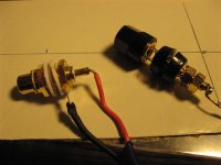
Yes, the washers are meant to give you the freedom to choose your ground point. Leave one of the input terminals without a washer on the back, ensuring that the back makes good contact with metal (remove any paint). Or, just leave all the washers on and choose a convenient point to be your chassis ground. This is what I typically do.
Ok let me get this straight as i'm a little confused from the light/dark green wiring diagrams: for non-cfb triode, i can just use an extra wire from one isolated input to ground stud on metal chassis, correct? I do not need to separately ground speaker terminals to chassis with another wire, right?
I'm a bit confused by your question, but you do need to separately ground the negative speaker terminals on each channel if you are not using CFB (which will get ground from the PCB). It's a safety issue. Making sure both OPT secondaries have a path to ground ensures that you don't get 100s of volts on the speakers if the insulation on one of the OPT windings ever fails.
- Status
- This old topic is closed. If you want to reopen this topic, contact a moderator using the "Report Post" button.
- Home
- More Vendors...
- Tubelab
- Simple SE grounding